Electrical alignments
GB 92
VR120
8.
Notes:
With varying frame amplitudes, the setting is made for the
greatest amplitude.
8.4
Front End (FV)
Service tasks after replacement of IC 7705, coil L5702 and
TUMOD:
8.4.1
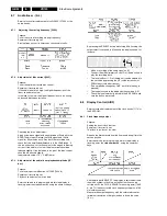
AFC Adjustment:
Purpose:
Correct adjustment of demodulator AFC - circuit
Symptom, if incorrectly set:
Bad or disturbed TV channel reception.
PAL - AFC adjustment [5702]:
SECAM band 1 - AFC adjustment [3730]: (SECAM L / L’
only)
Before commencing adjustment:
–
Switch to a band 1 SECAM L’ preset.
–
Is the system switch, in the menu ‘MANUAL
SEARCHING’, not possible, press the right cursor key of
the remote in the ‘CHANNEL NUMBER’ line for a short
moment.
–
A fine-tuning will be done and the system will switch to
the ‘AUTO’ function.
8.4.2
HF - AGC adjustment [3707]:
Service tasks after replacement of ICs 7705, or TUMOD:
Purpose:
Set amplifier control.
Symptom, if incorrectly set:
Picture jitter if input level is too low and picture distortion if
input level is too high.
8.4.3
Attenuating the 40.4 MHz [5704]: (SECAM only)
Service tasks after replacement of coil 5704:
Purpose:
To attenuate the band I carrier rests.
Symptom, if incorrectly set:
Bad picture quality when the filter attenuates the picture
carrier (38.9MHz).
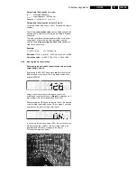
If the adjustment is correct the signal at pin 1 of SFW [1704]
must be smaller than the input signal amplitude by at least 5
dB.
A: AC, 50mV/Div, 20us/Div
REC
A
Summary of Contents for VR570
Page 12: ...Direction for use GB 12 VR120 3 3 Direction for use RT111 RT116 RT112 RT114 RT123 RT121 RT128 ...
Page 15: ...Direction for use GB 15 VR120 3 SAT VR870L VR870CC VR720 Set width 435 mm ...
Page 56: ...Service modes Repair tips GB 56 VR120 5 Engineer s remarks ...
Page 79: ...Circuit diagrams and PWB layouts Wiring diagram 79 VR120 7 7 16 Wiring Diagram Motherboard ...
Page 81: ...Circuit diagrams and PWB layouts Wiring diagram 81 VR120 7 Engineer s remarks ...
Page 82: ...82 VR120 7 Circuit diagrams and PWB layouts Wiring diagram Engineer s remarks ...
Page 83: ...Circuit diagrams and PWB layouts Wiring diagram 83 VR120 7 7 18 Mother board component side ...
Page 119: ...Tape deck GB 119 VR120 10 ...
Page 123: ...Tape deck GB 123 VR120 10 Engineer s remarks ...


