Electrical alignments
GB 93
VR120
8.
8.5
Deck electronics (DE)
Service tasks after replacement of IC 7463:
8.5.1
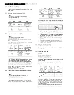
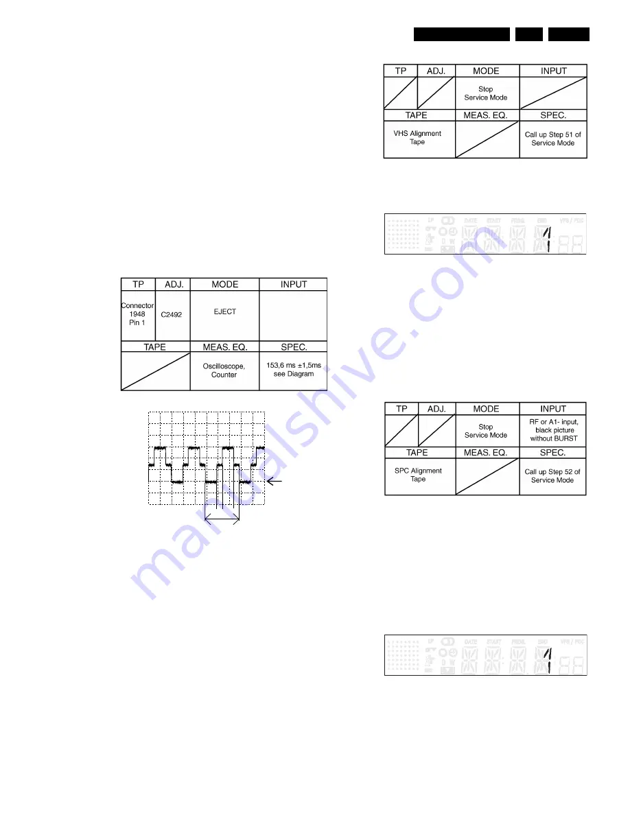
Motor frequency - adjustment [2492] (OPTION):
Purpose:
To adjust the working frequency of the head motor driver
(not necessary for M63100 BFP).
Result of an incorrect adjustment:
Head motor doesn’t start correctly.
Before commencing adjustment:
–
bring VCR in to EJECT state
–
disconnect set from main power source
–
remove cable 8004 from connector 1948
–
connect test point DRUM [9417] with 5VS1 [9869] (wires
on component side)
–
reconnect to main power source
8.6
Servo System (AIO1)
Service tasks after replacement of the head drum SYCA
7004-B or EEPROM.
8.6.1
Setting the gap position (GAP):
Purpose:
To determine the correct head switching point during
playback.
Symptom if incorrectly set:
Head switching fault and/or vertical picture flickers.
–
Enter the service test program and, whilst step display is
flashing, enter the step number 51, using the numerical
keys.
–
Insert a test cassette (e.g. 4822 397 30103) with the
standard video signal in the VCR.
–
By pressing the SELECT key whilst step 51 is flashing,
the automatic adjustment is triggered and stored in the
EEPROM .
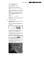
After a correct adjustment, the display shows 1;0 when
incorrect. In case of unsuccessful tuning the VCR ejects the
cassette. To leave the step, press SELECT.
Causes of incorrect adjustment :
Incorrect standard video signal.
Scanner fault.
Microprocessor fault.
8.6.2
”Studio Picture control” adjustment (SPC):
Purpose:
Adjustment of the reference level for the SPC.
Symptom if incorrectly set:
The picture is played back at a lower resolution than would
be possible.
–
Video signal via Scart or aerial
–
Enter the service test program and, whilst the step is
flashing, input the step number 52, using the numerical
keys.
–
Insert SPC Alignment Tape 4822 397 30268.
–
By pressing the SELECT key whilst step 52 is flashing,
the recorder makes a recording in SP mode (approx. 10
sec.) and in LP mode (approx. 10 sec.), rewinds and
carries out a playback with automatic adjustment.
–
After a correct adjustment the display shows 1, and 0 for
incorrect adjustments. In case of unsuccessful tuning the
VCR ejects the cassette.
To leave the step press SELECT.
0V
Connector 1948 PIN1-3
A: DC, 5V/DIV, 50ms/Div
153.6 ms = 6e
>
1e
2e
1e
2e
Summary of Contents for VR570
Page 12: ...Direction for use GB 12 VR120 3 3 Direction for use RT111 RT116 RT112 RT114 RT123 RT121 RT128 ...
Page 15: ...Direction for use GB 15 VR120 3 SAT VR870L VR870CC VR720 Set width 435 mm ...
Page 56: ...Service modes Repair tips GB 56 VR120 5 Engineer s remarks ...
Page 79: ...Circuit diagrams and PWB layouts Wiring diagram 79 VR120 7 7 16 Wiring Diagram Motherboard ...
Page 81: ...Circuit diagrams and PWB layouts Wiring diagram 81 VR120 7 Engineer s remarks ...
Page 82: ...82 VR120 7 Circuit diagrams and PWB layouts Wiring diagram Engineer s remarks ...
Page 83: ...Circuit diagrams and PWB layouts Wiring diagram 83 VR120 7 7 18 Mother board component side ...
Page 119: ...Tape deck GB 119 VR120 10 ...
Page 123: ...Tape deck GB 123 VR120 10 Engineer s remarks ...


