Electrical alignments
GB 94
VR120
8.
8.7
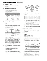
Audio linear - ( AL)
Service tasks after replacement of coil L5600, IC7004 or the
audio heads:
8.7.1
Adjusting the erasing frequency [5600]:
Purpose:
To set the correct recording erasing frequency.
Symptom, if incorrectly set:
Erasing frequency or its harmonics cause audio faults.
8.7.2
Adjustment of bias current [3625]:
Purpose:
To set the optimum record bias current.
Symptom, if incorrectly set:
If the audio level is too high, the higher frequencies of the
linear sound are too low.
If the level is too low, the higher frequencies are too strong
and sound distortions increase.
Checking the ’bias’ adjustment:
Apply a sine-wave signal with an amplitude of 50mVeff to the
SCART audio input. Record the 1kHz signal and 10kHz
signal for 30 seconds each. Play back the recording and
check that the amplitude difference is in the
±
3dB range. If
this is not the case, correct the value for the magnetic biasing
current. If the treble is too low, the bias current should be
reduced slightly. If the distortion is too great, the bias current
should be increased slightly.
(approximate value: +1V = -1dB Treble).
8.7.3
Adjustment of the audio linear playback amplitude [IIC-
bus]:
Purpose:
To set audio part amplification LA71595 [7004-A]
Symptom, if incorrectly set:
Playback sounds too low or too loud.
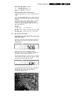
Enter the service test program and, whilst step display is
flashing, enter the step number 62, using the numerical keys.
By pressing the SELECT button whilst step 62 is flashing, the
output select is switched to Mono and the display shows, for
instance:
–
Make a recording of the audio signal on E1.
–
Connect the millivoltmeter to Scart1 Pin1(Audio out) and
play the recording back.
–
The level on Scart 1, Pin1 (Audio out) can be adjusted to
the set value by pressing the UP (value increases) or
DOWN keys (value decreases).
–
(The amplitude changes by 1 dB each time the key is
pressed).
–
The range is shown in the display by the numbers 0...31.
–
The value is automatically stored in the EE-PROM each
time the button is pressed.
8.8
Display Control (AIO2)
Service tasks after replacement of the clock quartz [1170] or
the EEPROM:
8.8.1
Clock frequency output
Purpose:
Setting the exact clock function.
Symptom, if incorrectly set:
The clock is too fast or too slow.
Remove the Motherboard from the frame and bring it into the
service position.
Enter the service test program and, whilst step display is
flashing, enter the step number 99, using the numerical
keys.
After entering with SELECT, the display is switched off and
the watch symbol is flashing, no further function can be
carried out. At the CLOCK ADJUST measuring point [7899-
A, pin 71], the uncorrected clock frequency of approx. 8192
Hz is always output.
Measure the output frequency with the calibrated counter
(minimum resolution of 6 digits) and note down the value
(f
mess
).
Summary of Contents for VR570
Page 12: ...Direction for use GB 12 VR120 3 3 Direction for use RT111 RT116 RT112 RT114 RT123 RT121 RT128 ...
Page 15: ...Direction for use GB 15 VR120 3 SAT VR870L VR870CC VR720 Set width 435 mm ...
Page 56: ...Service modes Repair tips GB 56 VR120 5 Engineer s remarks ...
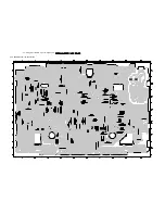
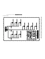
Page 79: ...Circuit diagrams and PWB layouts Wiring diagram 79 VR120 7 7 16 Wiring Diagram Motherboard ...
Page 81: ...Circuit diagrams and PWB layouts Wiring diagram 81 VR120 7 Engineer s remarks ...
Page 82: ...82 VR120 7 Circuit diagrams and PWB layouts Wiring diagram Engineer s remarks ...
Page 83: ...Circuit diagrams and PWB layouts Wiring diagram 83 VR120 7 7 18 Mother board component side ...
Page 119: ...Tape deck GB 119 VR120 10 ...
Page 123: ...Tape deck GB 123 VR120 10 Engineer s remarks ...


