Electrical alignments
GB 96
VR120
8.
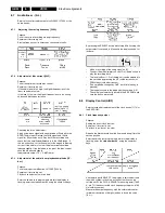
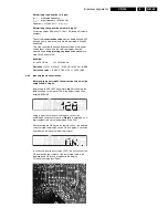
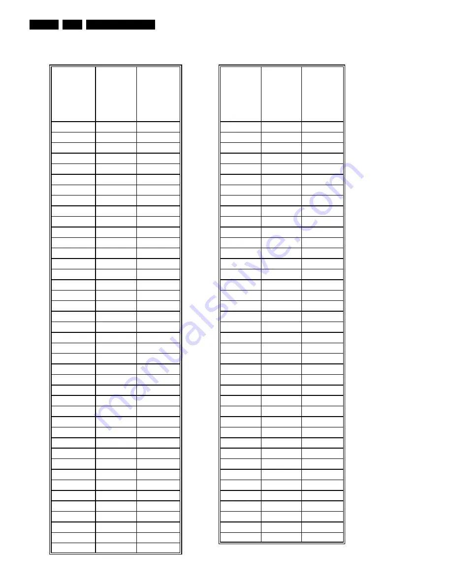
Adjustment table of the clock frequency:
Measured frequency in Hertz:
measured
clock
frequency
pos. 7899-A
pin 71
[Hz]
corrected
value
for Step 53
input
Time
deviation
minutes /
year
measured
clock
frequency
pos. 7899-A
pin 71
[Hz]
corrected
value
for Step 53
input
Time
deviation
minutes /
year
8192,00
128
0,0
8192,00
128
0,0
8191,98
125
-1,2
8192,02
131
1,2
8191,96
122
-2,4
8192,04
134
2,4
8191,94
118
-3,7
8192,06
138
3,7
8191,92
115
-4,9
8192,08
141
4,9
8191,90
112
-6,1
8192,10
144
6,1
8191,88
109
-7,3
8192,12
147
7,3
8191,86
106
-8,5
8192,14
150
8,5
8191,84
102
-9,8
8192,16
154
9,8
8191,82
99
-11,0
8192,18
157
11,0
8191,80
96
-12,2
8192,20
160
12,2
8191,78
93
-13,4
8192,22
163
13,4
8191,76
90
-14,6
8192,24
166
14,6
8191,74
86
-15,9
8192,26
170
15,9
8191,72
83
-17,1
8192,28
173
17,1
8191,70
80
-18,3
8192,30
176
18,3
8191,68
77
-19,5
8192,32
179
19,5
8191,66
74
-20,8
8192,34
182
20,8
8191,64
70
-22,0
8192,36
186
22,0
8191,62
67
-23,2
8192,38
189
23,2
8191,60
64
-24,4
8192,40
192
24,4
8191,58
61
-25,6
8192,42
195
25,6
8191,56
58
-26,9
8192,44
198
26,9
8191,54
54
-28,1
8192,46
202
28,1
8191,52
51
-29,3
8192,48
205
29,3
8191,50
48
-30,5
8192,50
208
30,5
8191,48
45
-31,7
8192,52
211
31,7
8191,46
42
-33,0
8192,54
214
33,0
8191,44
38
-34,2
8192,56
218
34,2
8191,42
35
-35,4
8192,58
221
35,4
8191,40
32
-36,6
8192,60
224
36,6
8191,38
29
-37,8
8192,62
227
37,8
8191,36
26
-39,1
8192,64
230
39,1
8191,34
22
-40,3
8192,66
234
40,3
8191,32
19
-41,5
8192,68
237
41,5
8191,30
16
-42,7
8192,70
240
42,7
8191,28
13
-43,9
8192,72
243
43,9
8191,26
10
-45,2
8192,74
246
45,2
8191,24
6
-46,4
8192,76
250
46,4
8191,22
3
-47,6
8192,78
253
47,6
8191,20
0
-48,8
Summary of Contents for VR570
Page 12: ...Direction for use GB 12 VR120 3 3 Direction for use RT111 RT116 RT112 RT114 RT123 RT121 RT128 ...
Page 15: ...Direction for use GB 15 VR120 3 SAT VR870L VR870CC VR720 Set width 435 mm ...
Page 56: ...Service modes Repair tips GB 56 VR120 5 Engineer s remarks ...
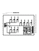
Page 79: ...Circuit diagrams and PWB layouts Wiring diagram 79 VR120 7 7 16 Wiring Diagram Motherboard ...
Page 81: ...Circuit diagrams and PWB layouts Wiring diagram 81 VR120 7 Engineer s remarks ...
Page 82: ...82 VR120 7 Circuit diagrams and PWB layouts Wiring diagram Engineer s remarks ...
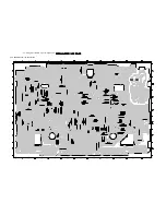
Page 83: ...Circuit diagrams and PWB layouts Wiring diagram 83 VR120 7 7 18 Mother board component side ...
Page 119: ...Tape deck GB 119 VR120 10 ...
Page 123: ...Tape deck GB 123 VR120 10 Engineer s remarks ...


