background image

Dear Customer,

Congratulations on buying your Phocos product! Please read the instructions carefully and thoroughly before using the product. It comes with a number 

of outstanding features, such as:

Maximum Power Point Tracking technology, which increases the efficiency of your PV system 

Positive grounding

Dimming function

Case protection: IP68, in 1.5 m deep water 72 hours

Control unit (CIS-CU) to configure CIS-MPPT 50/10 charge controller, via infra-red data link

External temperature sensor for temperature compensation of charging voltages

4 stage charging (main, boost, equalization, float) for flooded battery; 3 stage charging (main,boost, float) for sealed battery

Automatic recognition of system voltage 12/24 V

Widely programmable


General Safety Information

This manual contains important installation, set up, and safety operating instructions.
Please read the instructions and warnings in this manual carefully before beginning any installation.
Please do not disassemble or attempt to repair Phocos products. Phocos charge controllers do not contain user serviceable parts.
Please observe all instructions with regards to external fuses/breakers as indicated.
The information contained in this manual must be observed in its  full extent. The manual contains information regarding installation, set up, and 

operation.
Please read this manual carefully before using the product, and pay special attention to the safety recommendations in it.

Maintenance and installation notes 

When installing or working on the PV system, please disconnect the PV (solar) modules from the charge controller first, to prevent any damages to the 

charge controller!
Please verify that all cable/wire connections are done properly and well insulated and that no water or humidity can ingress  in order to avoid any bad or 

13

Summary of Contents for CIS-MPPT 50/10

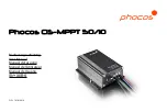
Page 1: ...Phocos CIS MPPT 50 10 Bedienungsanleitung User Manual Manual del usuario Manuel de l utilisateur Manual de Usu rio CID 181816410...

Page 2: ...CONTENTS Bedienungsanleitung User Manual Manual de Instrucciones Guide de l utilisateur Manual do Usu rio 1 12 13 24 25 36 37 48 49 60 61 72...

Page 3: ...ngen f r die Installation den Anschluss und sicheren Betrieb Bevor Sie mit der Installation beginnen lesen Sie bitte sorgf ltig die im Handbuch aufgef hrten Anweisungen und Warnhinweise Bitte versuche...

Page 4: ...e keinesfalls kurzzuschlie en Verwenden Sie ausschlie lich isoliertes Werkzeug Der Betrieb dieses Ger tes kann Hochspannung erzeugen was bei unsachgem er Installation oder Verwendung zu schweren Verle...

Page 5: ...chte Spannungsverteilung an den Kabeln zu vermeiden verbinden Sie zuerst die Kabel am Laderegler dann an der Batterie Modul oder Last Der empfohlene mind Kabeldurchmesser betr gt 4 mm Stellen Sie sich...

Page 6: ...4 Zum Kontroll Dimm Steuer eingang der LED Treiber Erdungs Stelle Sich erung...

Page 7: ...uss COMMON 2 5 mm2 rot Negativer Lastanschluss LOAD 2 5 mm2 gr n Dimm Signal Anschluss 0 25 mm2 schwarz Display und Warnfunktion LED Status Funktion An Laderegler ist mit der Batterie verbunden Nachte...

Page 8: ...Tagedauernbis der Laderegler pr zisedieNachtmitte gelernt hat Nachtmitte kann von00 00 Mitternacht abweichen abh ngig vonIhremStandort Der Laderegler erkennt Tag und Nacht basierend auf der Leerlaufs...

Page 9: ...nute an Sollte das Dr cken der Taste einen Lastabwurf LVD Tiefentladeschutz SOC berstrom verursachen wird dieLastsofort ausgeschaltet Sicherheitsfunktion PV Anschluss Batterie Anschluss Last Anschluss...

Page 10: ...aderegler verursachen Bitte beheben Sie zuerst den Fehler bevor Sie mit dem Anschlie en des Ladereglers fortfahren Tiefentladeschutz Funktion LVD Ladezustandsgesteuert SOC Abschaltung bei 11 00 22 00...

Page 11: ...kennt Tag und Nacht basierend auf der Leerlaufspannung der Solaranlage Diese Tag Nacht Schwelle kann den lokalen Lichtverh ltnissen und der verwendeten Solaranlage angepasst werden Um die richtigen We...

Page 12: ...8 27 6 V 25 C Hauptladung 14 4 V 25 C 0 5 h t glich Boost Ladung 14 4 28 8 V 25 C 2 h Aktivierung Batteriespannung 12 3 24 6 V Ausgleichsladung 14 8 29 6 V 25 C 2 h Aktivierung Batteriespannung 12 1...

Page 13: ...V Schrittweite 0 5 1 0 V 4 0 11 5 V 8 0 23 0 V Schrittweite 0 5 1 0 V Kabell nge 20 cm Abmessung BXHXT 88 5 x 112 x 41 4 mm Gewicht 625 g Kabeldurchmesser AWG 13 2 5 mm2 Schutzart IP68 1 5 m 72 h Dim...

Page 14: ...des Batterieherstellers missachtet werden Der Hersteller haftet nicht wenn Reparaturen oder Kundendienst von nicht autorisierten Personen durchgef hrt wurden bei unsachgem er Gebrauch falscher Instal...

Page 15: ...ation set up and safety operating instructions Please read the instructions and warnings in this manual carefully before beginning any installation Please do not disassemble or attempt to repair Phoco...

Page 16: ...Use only tools with insulated handles Operation of this device may produce a high voltage which could cause severe injuries or death in case of improper installation or operation of the device PV mod...

Page 17: ...void any installation faults To avoid any damaging voltage on the wires first connect the wire to the controller then to the battery to the panel or to the load Minimum recommended wire size 4 mm Make...

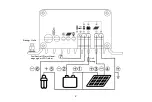
Page 18: ...16 Connect to dimming control terminal of LED Driver Grounding post Fuse...

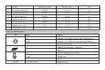
Page 19: ...itive load terminal COMMON AWG 13 2 5 mm2 Red Negative load terminal LOAD AWG 13 2 5 mm2 Green Dimming signal terminal AWG 24 0 25 mm2 Black LED indications warning functions LED Status Function On Co...

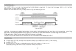
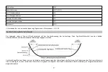
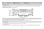
Page 20: ...days until the controller has learned the middle of the night precisely Middle of night may be different from 12 00 midnight depending on your location longitude The controller recognizes day and nigh...

Page 21: ...Function Pushing the test button on the CIS CU Control Unit will switch on load terminal for 1 minute Should pressing the button cause a load disconnect event LVD SOC over current then the load will...

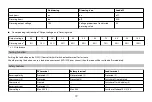
Page 22: ...onnects with 10s delay 110 nominal current disconnects with 120s delay 7 MPPT switches off when detecting reverse current 8 At voltages above 50 V the MPPT will stop charging WARNING The combination o...

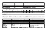
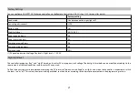
Page 23: ...50 1 PV panel open circuit voltage Day level Night level 1 5 3 0 V Night light level The controller recognizes day and night based on the solar PV array open circuit voltage The daylight threshold ca...

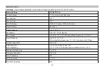
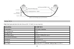
Page 24: ...IS MPPT 50 10 System voltage 12 24 V auto recognition Max charge current 10 A Max load current 10 A Max PV input power 150 W 12 V 300 W 24 V system Power conversion efficiency Up to 98 Float charge 13...

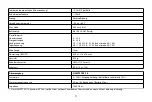
Page 25: ...tage protection 10 5 21 0 V Max PV voltage 50 V Min PV voltage 17 34 V Max battery voltage 50 V Temperature compensation charge voltage 4 2 mV K per cell Self consumption 10 mA Grounding Positive grou...

Page 26: ...eously Liability Exclusion The manufacturer shall not be liable for damages especially on the battery caused by use other than as intended or as mentioned in this manual or if the recommendations of t...

Page 27: ...ara bater a sellada Reconocimiento autom tico de tensi n del sistema 12 24 V Ampliamente programable Informaci n general de seguridad Este manual contiene instrucciones de funcionamiento importantes d...

Page 28: ...aje con el equipo el ctrico activado energizado Cuando se trabaja alrededor de a una bater a no permita deje herramientas cerca para proteger las terminales de la bater a o cortocircuito en cualquier...

Page 29: ...er falla de instalaci n Para evitar cualquier voltaje perjudicial en los cables primero conecte el cable al controlador luego a la bater a panel o a la carga Tama o m nimo recomendado para el cable 4m...

Page 30: ...28 Punto de puesta a tierra Conecte al terminal de control de atenuaci n del controlador LED Fusi ble...

Page 31: ...5 mm2 rojo Terminal negativo de carga LOAD AWG 13 2 5 mm2 verde Terminal de se al de atenuaci n AWG 24 0 25 mm2 negro Indicadores LED y funciones de advertencia LED Estado Funci n Encendido Controlad...

Page 32: ...s detectada autom ticamente como el punto medio entre el crep sculo y el amanecer no se requiere ninguna configuraci n de un reloj Pueden pasar varios d as hasta que el controlador haya aprendido la m...

Page 33: ...taje proporcional al valor de atenuaci n de ajuste 0 V Relaci n correspondiente del voltaje de salida y el valor de atenuaci n Voltaje de salida 0 V 1 V 2 V 3 V 4 V 5 V 6 V 7 V 8 V 9 V 10 V Valor de a...

Page 34: ...a da arse permanentemente en caso de cortocircuito 6 200 corriente nominal desconexi n con 3s de retraso 150 corriente nominal desconexi n con 10s de retraso 110 corriente nominal desconexi n con 120...

Page 35: ...rolador est ndar luz nocturna apagada Desconexi n por bajo voltaje SOC4 Tipo de bater a Gel Nivel de luz nocturna 8 0 16 0 V 1 Horas nocturnas de carga 0 h Horas diurnas de carga 0 h Horas nocturnas d...

Page 36: ...secci n de programaci n Datos t cnicos Nota Los niveles de voltaje antes y despu s de la barra son v lidos para sistemas de 12 V y 24 V respectivamente Datos t cnicos CIS MPPT 50 10 Voltaje del siste...

Page 37: ...nexi n 12 8 25 6 V Protecci n contra bajo voltaje 10 5 21 0 V M x voltaje del panel 50 V M n voltaje del panel 17 34 V M x voltaje de la bater a 50 V Compensaci n de temperatura voltaje de carga 4 2 m...

Page 38: ...rga no simult neamente Exclusi n de responsabilidad El fabricante no se har responsable por da os especialmente a la bater a por otro uso que no sea el previsto o mencionado en este manual o si no se...

Page 39: ...programmable Informations g n rales sur la s curit Le pr sent manuel contient des instructions d installation de configuration de fonctionnement et des consignes de s curit Veuillez lire les consignes...

Page 40: ...s outils n effectuent pas de pontage entre les bornes de la batterie ni ne provoquent de court circuit de la batterie N utilisez que des outils poign es isolantes Le fonctionnement de cet appareil peu...

Page 41: ...r viter des erreurs d installation Pour viter des dommages dus la tension circulant dans les fils branchez d abord le c ble sur le r gulateur puis sur la batterie le panneau ou sur la charge Dimension...

Page 42: ...40 Connectez au terminal de contr le du gradateur du pilote LED Mise la terre Fusi ble...

Page 43: ...13 2 5 mm2 rouge Borne n gative de la charge LOAD AWG 13 2 5 mm2 vert Borne du signal de gradation AWG 24 0 25 mm2 noir Indications des LED et fonctions de mise en garde LED Statut Fonction Activ e R...

Page 44: ...saire de proc der au r glage d une horloge Plusieurs jours peuvent passer avant que le r gulateur n identifie avec pr cision le milieu de la nuit Selon votre position longitude il est possible que le...

Page 45: ...ur de gradation 0 V Correspondance entre tension de sortie et valeur de gradation Tension de sortie 0 V 1 V 2 V 3 V 4 V 5 V 6 V 7 V 8 V 9 V 10 V Valeur de gradation 0 10 20 30 40 50 60 70 80 90 100 To...

Page 46: ...e sinon elle sera irr m diablement endommag e en cas de court circuit 6 200 courant nominal d connexion au bout de 3 s 150 courant nominal d connexion au bout de 10 s 110 courant nominal d connexion a...

Page 47: ...Charge 1 soir e 0 h Charge 1 matin 0 h Gradation soir e 0 h Gradation matin 0 h Taux de gradation 50 1 Circuit en tension ouverte du panneau Niveau du jour Niveau de la nuit 1 5 3 0 V Niveau d clairag...

Page 48: ...e automatique 12 24 V Courant de charge max 10 A Courant max de chargement 10 A Puissance d entr e PV maxi 150 W syst me 12V 300 W syst me 24 V Taux de rendement de conversion d nergie Jusqu 98 Charge...

Page 49: ...Tension max du panneau solaire 50 V Tension min du panneau solaire 17 34 V Tension max de la batterie 50 V Compensation thermique tension charge 4 2 mV K par cellule Autoconsommation ralenti 10 mA Mis...

Page 50: ...nt ne pourra tre tenu responsable des dommages plus particuli rement concernant la batterie r sultant d une utilisation autre que celle pour laquelle l appareil est pr vu telle qu elle est d crite ou...

Page 51: ...tala o configura o e opera o importantes Leia as instru es e avisos neste manual com aten o antes de come ar a executar qualquer instala o N o desmonte ou tente reparar os produtos Phocos Os controlad...

Page 52: ...r tens es elevadas que poder o causar les o grave ou morte em caso de instala o ou opera o indevida Os m dulos PV podem gerar tens o elevada em C C Certifique se de que todos os condutores estejam sem...

Page 53: ...ve que os terminais positivos do controlador CIS MPPT 50 10 s o conectados internamente entre si e por isso t m o mesmo potencial el trico Caso seja necess rio uma conex o de aterramento ent o sempre...

Page 54: ...52 Conecte ao terminal de controle de luminosidade do LED Driver Ponto de aterramento Fus vel...

Page 55: ...rde Sequencialmente Programa o Fun o Luz Noturna O controlador CIS MPPT 50 10 fornecido com sofisticada fun o luz noturna Controla a sa da carga durante a noite sendo tamb m amplamente program vel Est...

Page 56: ...10 V relativa ao p lo negativo da bateria ajusta passo 1 V 3 de toler ncia Imped ncia de 1 000 Ohms Horas de carga Load 1 no painel da UC e horas de fluxo luminoso Load 2 no painel da UC funciona em c...

Page 57: ...Protegido Protegido 5 Desconex o imediata Corrente alta Limitado Desconecta com retardo 6 Corrente inversa Protegido 7 Tens o alta M x 50 V 8 M x 50 V Desliga acima de 15 5 31 0 V Tens o baixa Deslig...

Page 58: ...4 V a 11 76 23 52 V SOC2 11 25 22 50 V a 11 83 23 63 V SOC3 11 38 22 72 V a 11 89 23 78 V SOC4 11 51 23 02 V a 11 96 23 92 V SOC5 11 64 23 28 V a 12 02 24 04 V SOC6 Controlado por tens o LVD desconect...

Page 59: ...urna O controlador distingue entre dia e noite baseado na tens o de circuito aberto do painel solar O limite de luz diurna pode ser ajustado de acordo com os requisitos das condi es locais e o tipo de...

Page 60: ...98 Tens o de flutua o 13 8 27 6 V 25 C Tens o de carga principal 14 4 V 25 C 0 5 h di ria Tens o de carga r pida Boost 14 4 28 8 V 25 C 2 h Ativa o tens o de bateria 12 3 24 6 V Equaliza o 14 8 29 6 V...

Page 61: ...n vel do mar Tipo de bateria Chumbo cida GEL AGM flutua o Faixa de ajuste Horas noturnas Horas diurnas Detec o noite Detec o dia 0 15 h 0 14 h 2 5 10 0 V 5 0 20 0 V passo ajust vel 0 5 1 0 V 4 0 11 5...

Page 62: ...causados pelo uso indevido al m destes especificados neste manual ou se as recomenda es do fabricante de bateria forem negligenciadas O fabricante n o ser respons vel se o equipamento for reparado por...

Page 63: ...CIS MPPT 50 10 IP68 1 5 m 72 CIS CU 4 3 12 24 V CIS MPPT 50 10 61...

Page 64: ...CE CE MPPT 98 IP68 40 C 60 C 62...

Page 65: ...wwwwww wwwwwww wwwwwww wwwwwww wwwwww 4 0 mm2 CIS MPPT 50 10 COMMON AWG 13 2 5 mm2 BATTERY AWG 13 2 5 mm2 COMMON AWG 13 2 5 mm2 SOLAR AWG 13 2 5 mm2 COMMON AWG 13 2 5 mm2 LOAD AWG 13 2 5 mm2 AWG 24 0...

Page 66: ...64...

Page 67: ...CIS MPPT 50 10 3 65...

Page 68: ...0 V 10 V 1 V 1000 Ohm CIS CU 1 CIS CU 2 N A 10 V 0 V 66...

Page 69: ...0 V 1 V 2 V 3 V 4 V 5 V 6 V 7 V 8 V 9 V 10 V 0 10 20 30 40 50 60 70 80 90 100 3 CIS CU Test 1 CIS MPPT 50 10 LVD LVD 1 2 3 4 5 6 7 50 V 8 50 V 15 5 31 0 V 1 2 67...

Page 70: ...1 00 22 00 V 11 70 23 40 V SOC1 11 12 22 24 V 11 76 23 52 V SOC2 11 25 22 50 V 11 83 23 63 V SOC3 11 38 22 72 V 11 89 23 78 V SOC4 11 51 23 02 V 11 96 23 92 V SOC5 11 64 23 28 V 12 02 24 04 V SOC6 LVD...

Page 71: ...8 0 16 0 V 1 0 h 0 h 0 h 0 h 50 1 1 5 3 0 V 69...

Page 72: ...A 150 W 12 V 300 W 24 V 98 13 8 27 6 V 25 C 14 4 V 25 C 0 5 h 14 4 28 8 V 25 C 2 12 3 24 6 V 14 8 29 6 V 25 C 2 12 1 24 2 V 30 15 5 31 0 V 10 5 21 0 V 11 00 12 02 22 00 24 04 V 11 0 11 9 22 0 23 8 V 0...

Page 73: ...0 mA 40 60 C 4 000 AGM 0 15 h 0 14 h 2 5 10 0 V 5 0 20 0 V 0 5 1 0 V 4 0 11 5 V 8 0 23 0 V 0 5 1 0 V 20 cm WXHXD 88 5 x 112 x 41 4 mm 625 g AWG 13 2 5 mm2 IP68 1 5 m 72 h CIS MPPT 50 10 0 100 10 0 V 1...

Page 74: ...20140715 Phocos AG Germany www phocos com 72 ISO9001 RoHS...

Reviews: