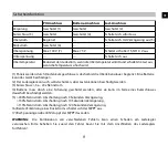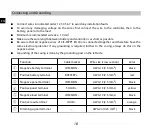
Connecting and Grounding
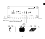
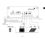
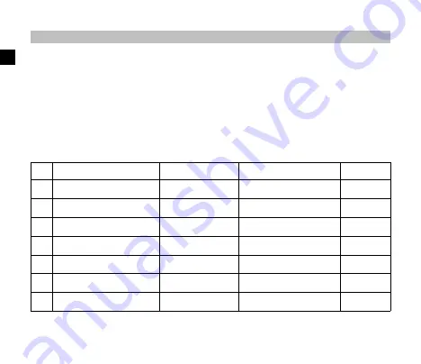
Connect wires in indicated order 1 2 3 4 5 6 7 to avoid any installation faults
To avoid any damaging voltage on the wires, first connect the wire to the controller, then to the
battery, panel or to the load
Minimum recommended wire size: 10 mm²
Make sure the wire length between battery and controller is as short as possible
Be aware that all negative wires of CIS-MPPT 85/20 are connected together and therefore have the
same electrical potential. If any grounding is required further to the casing, always do this on the
negative wires.
Grounding of the casing is done by the grounding post on the left side.
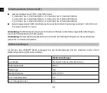
Function
Cable marker
Wire size (cross section)
Color
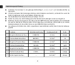
①
Negative battery terminal
COMMON -
AWG 13 (2.5 mm
2
)
black
②
Positive battery terminal
B
AWG 13 (2.5 mm
2
)
red
③
Negative panel terminal
COMMON -
AWG 13 (2.5 mm
2
)
black
④
Positive panel terminal
SOLAR +
AWG 13 (2.5 mm
2
)
yellow
⑤
Negative load terminal
COMMON -
AWG 13 (2.5 mm
2
)
black
⑥
Positive load terminal
LOAD +
AWG 13 (2.5 mm
2
)
orange
⑦
Dimming signal terminal
---
AWG 24 (0.25 mm
2
)
black
18
EN
Summary of Contents for CIS-MPPT 85/20
Page 7: ...5 Zum Kontroll Dimm Steuer eingang der LED Treiber extern Erdungs Stelle Sicherung DE...
Page 21: ...19 Connect to dimming control terminal of LED Driver external Grounding Post Fuse EN...
Page 74: ...CE CE 72 CH...
Page 75: ...MPPT 98 IP68 40 C 60 C 12 24 V 73 CH...
Page 77: ...75 CH...
Page 78: ...CIS MPPT 85 20 3 76 CH...
Page 79: ...77 CH...
Page 83: ...0 h 50 1 1 5 3 0 V 81 CH...

