CIS05/10/20
Solar Charge Controller with Programmable Night-Light Function User Manual (English)
Dear customer, thank you very much for buying this Phocos product. Please read the instructions
carefully and thoroughly before using the product. It comes with a number of outstanding
features, such as:
Case protection: IP68 protection, in 1.5 m water depth 72 Hours.
Dimming function
Control unit (CU) to configure CIS charge controller via infra-red data link
External temperature sensor for temperature compensation of charge voltages
Widely programmable
3 stage charging (boost, equalization, float) for flooded battery, 2 stage charging (boost,
float) for sealed battery
Automatic recognition of system voltage 12/24 V
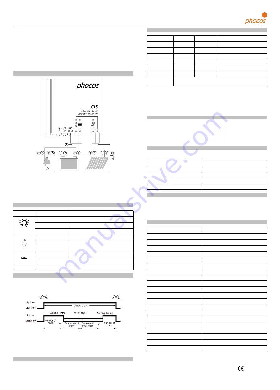
Connecting and Grounding
Connect wires in order indicated 1 2 3 4 5 6 7 to avoid installation faults.
To avoid any voltage on the wires, first connect the wire to the controller, then to the
battery, panel or load.
Recommended minimum wire size: CIS05: 1.5 mm
2
; CIS10: 2.5 mm
2
; CIS20: 4 mm
2
.
Make sure the wire length between battery and controller is as short as possible.
Be aware that the positive terminal of CIS are connected together and therefore have the
same electrical potential. If any grounding is required, always do this on the positive wires
.
Display & Warning Functions
LED
Staus
Function
0n
Controller connected to battery, night detected
Flash
Controller connected to battery, day detected
Off
No battery connected
On
Load low/high voltage disconnect(LVD/HVD)
Flash
Load over current
Off
Load OK
On
Dimming because of LVD/HVD
Off
Time controlled dimming
All LED
Green-->Red-->Green-->
Programming
Night-Light Function
The CIS controller comes with a sophisticated night-light function. It controls the load output
at night and is widely programmable.
There are 3 modes available:
Standard Controller, Dusk to Dawn and Evening/Morning modes.
"Middle of night" is detected automatically as the midpoint between dusk and dawn, no setting of a
clock is required. It may take several days until the controller has "learned" the middle of the night
precisely. "Middle of night" may be different from 12:00 midnight depending on your location.
The controller recognizes day and night based on the solar array open circuit voltage.
This day/night threshold can be modified according to local light conditions and the solar
array used.
Testing Function
Pushing the test button on the CU (Control Unit) will switch on load terminal for 2 minutes.
If pressing the button causes a load disconnect event (LVD/SOC, over current) the load will be
switched off.
Safety Features
Solar terminal
Battery terminal
Load terminal
Reverse polarity
Protected (1)
Protected (1)
Protected (2)
Short circuit
Protected
Protected (3)
Switches off immediately
Over current
N/A
N/A
Switches off with delay
Reverse current
Protected
N/A
N/A
Over voltage
Max. 55V (4)
Max. 40V
Switches off above 15.5V / 31.0V
Under voltage
N/A
N/A
Switches off
Over temp.
Reduces the charging current by PWM if over temperature occurs and
switches off the load if the temperature reaches a high level.
(1) Controller can not protect itself in a 24V system; Upanel-Ubattery is limited to 40V.
(2) Controller can protect itself, but loads might be damaged.
(3) Battery must be protected by fuse, or battery will be permanently damaged.
(4) The solar panel voltage should not exceed this limit for a long time as voltage protection
is done by a varistor.
WARNING: The combination of different error conditions may cause damage to the controller.
Always remove the error before you continue connecting the controller!
Low Voltage Disconnect Function (LVD)
State of charge (SOC) controlled: Disconnect at 11.00V/22.00V to 11.70/23.40V(SOC1),
11.12V/22.24V to 11.76/23.52V(SOC2), 11.25V/22.50V to 11.83/23.63V(SOC3),
11.38V/22.72V to 11.89/23.78V(SOC4), 11.51V/23.02V to 11.96/23.92V(SOC5),
11.64V/23.28V to 12.02/24.04V(SOC6) .
Voltage controlled (LVD): Disconnect at a fixed voltage between 11.0/22.0V and
11.9/23.8V (Step 0.1V).
Factory Settings
You can configure CIS charge controllers via the Control Unit (CU). See CU manual for details.
Factory setting
Load mode
Standard controller
Low voltage disconnect
SOC4
Battery type
Sealed
Dimming value
50 %
Liability Exclusion
The manufacturer shall not be liable for damages, especially on the battery, caused by use
other than as intended or as mentioned in this manual or if the recommendations of the
battery manufacturer are neglected. The manufacturer shall not be liable if there has been
service or repair carried out by any unauthorized person, unusual use, wrong installation, or
bad system design.
Technical Data
Nominal voltage
12/24 V, automatic recognition
Boost voltage
14.4/28.8 V (25 °C), 2 h
Equalization voltage
14.8/29.6 V (25 °C), 2 h
Float voltage
13.8/27.6 V (25 °C)
Load disconnect voltage
11.00-12.02 V/22.00-24.04 V By SOC
11.0-12.0 V/22.0-24.0 V By voltage
Load reconnect voltage
12.8/25.6 V
Evening hours /Morning hours
0-15 hours / 0-14 hours
Dimming value
0…100 % output power
Dimming output voltage
0 V to 5 V relative to battery minus
Night/day detect
2.5-10 V
Battery type
Flooded, Sealed
Temp. compensation
-4.2 mV/K per cell
Max. solar current
5/10/20, According to model number @ 60 °C
Max. load current
5/10/20, According to model number @ 60 °C
Dimensions
82 x 58 x 20 mm
Wire size
CIS05: 1.5 mm
2
; CIS10: 2.5 mm
2
; CIS20: 4 mm
2
Typical power consumption
Lower than 8/10mA
Ambient temp. range**
-40 to +60 °C
Case protection
IP68 (1.5 m, 72 h)
Max altitude / Weight
4000 m / 150 g
**
:
At 60°C CIS can only have full current on panel or load, not together.
S
ubject to change without notice. Version: 20100309
Made in one of the following countries:
Germany - China - Bolivia - India
Phocos AG - Germany www.phocos.com
CID:181812421
ISO9001
RoHS
To dimming termianl of lamp


