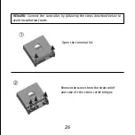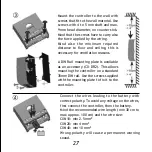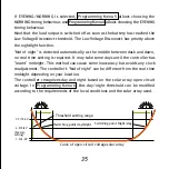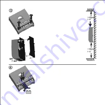
Mount the controller to the wall with
screws that fit to the wall material. Use
screws with 4 to 5 mm shaft and max.
9 mm head diameter, no counter sink.
Mind that the screws have to carry also
the force applied by the wiring.
Mind also the minimum required
distance to floor and ceiling, this is
necessary for ventilation reasons.
A DIN Rail mounting plate is available
as an accessory (CX-DR2). This allows
mounting the controller on a standard
35mm DIN rail. Use the screws supplied
with the mounting plate to fix it to the
controller.
27
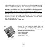
Connect the wires leading to the battery with
correct polarity. To avoid any voltage on the wires,
first connect the controller, then the battery.
Mind the recommended wire length (min 30 cm to
max approx. 100 cm) and the wire size:
CXN10: min 2.5 mm
2
CXN20: min 4 mm
2
CXN40: min 10 mm
2
Wrong polarity will cause a permanent warning
sound.
Summary of Contents for CXN Series
Page 1: ...Phocos CXN CID NO 181811101...
Page 2: ...1 22 23 44 45 66 67 88 89 110 111 132 CONTENTS...
Page 118: ...Phocos CXN 111...
Page 119: ...112...
Page 120: ...113...
Page 121: ...114...
Page 122: ...115...
Page 123: ...116...
Page 124: ...117...
Page 125: ...118...
Page 126: ...119...
Page 127: ...120 80 60 80 35 60 10 35 10 1x 2x 3x 4x 5x...
Page 128: ...121...
Page 129: ...122...
Page 130: ...123 1 2 1 2...
Page 131: ...124 7 7 15 4V 4 9 9 8V 1 0 2 0V...
Page 132: ...125...
Page 133: ...126...
Page 134: ...127...
Page 135: ...128...
Page 136: ...129...
Page 137: ...130...
Page 138: ...131...
Page 139: ...132 RoHS ISO9001 2000...

