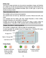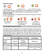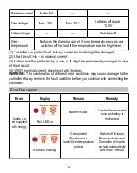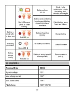
Connecting and Grounding
The controller is intended for indoor use only. Protect it from direct sunlight and
preferrably place it in a dry environment. Please verify that all cable/wire connections
are done properly and well insulated and that no water or humidity can ingress. This
avoids any bad or loose connections that would result in excessive heating or further
damage. The controller measures the ambient temperature to determine the charging
voltage. Controller and battery must be installed in the same room. The controller
warms up during operation, and should therefore be installed on a non flammable
surface only. Connect the controller by following the steps described below to avoid
installation faults.
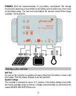
Observe the following connection sequence when installing the system:
1. Connect the battery to the charge controller – plus and minus.
2. Connect the photovoltaic modules to the charge controller – plus
and minus.
3. Connect the load to the charge controller – plus and minus.
Follow the reverse procedure when uninstalling!
Additionally, to avoid any voltage on the wires, first connect the wire to the
controller, then to the battery, photovoltaic modules. But for load, first connect
the wire to the load, then to the controller.
Recommended minimum wire size: 4 mm
2
;
Make sure the wire length between battery and controller is as short as possible.
Be aware that all negative connections of the ECO-N controller are common and
therefore have the same electrical potential. If any grounding is required, always
do this on the negative wire.
When connecting inductive loads (motors, relays, etc.), a freewheel diode must
be connected in parallel to the loads in the reverse biased direction.
Due to their high inrush currents, large inverters should always be connected
directly to the battery.
REMARK:
If the device is used in a vehicle which has the battery negative pole
connected to the chassis, than any loads connected to the controller must not have
an electric connection to the car body. Otherwise the Low Voltage Disconnect function
and the electronic fuse function of the controller will become impaired (short
circuited).
12

