background image

15

NOTA: Conecte el MPPT siguiendo los pasos descritos a continuación para evitar problemas en la instalación.

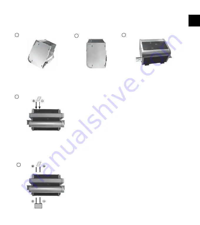
Por favor, vea las Fig 1,2 y 3 en las que se muestra como instalar el MPPT en un carril DIN estándar de 35mm.
Asegúrese que la ventilación lateral no esté obstruida.
Monte el carril DIN en la superficie vertical. Monte el MPPT de forma que asegure suficiente espacio inferior 
y superior para que el aire fluya verticalmente a través de las ranuras de ventilación.

Abra la tapa en el lado de la batería. Conecte con la polaridad 
correcta los cables que van a la batería. Para evitar el voltaje en 
los cables, conecte primero el MPPT y luego la batería. Utilice el 
tamaño de cable recomendado (ver tabla en el capítulo cableado 
recomendado 
para MPPT100/30).Cierre la tapa del lado de la batería.

Conecte con la polaridad correcta los cables que van al módulo solar. 
Para evitar cualquier voltaje de los cables, conecte primero el 
controlador y luego el módulo solar. Utilice el tamaño de cable 
recomendado (ver tabla en el capítulo cableado recomendado 
para MPPT100/30).
Cierre la tapa del lado del panel solar.

NOTA: Los paneles solares proporcionan voltaje desde el momento que reciben luz solar. Siga las recomendaciones 
del fabricante del panel solar.

NOTA: Ponga los cables positivo y negativo juntos para minimizar los efectos electromagnéticos.

1

3

5

4

una superficie no inflamable.

2

ES

Summary of Contents for MPPT100/30

Page 1: ......

Page 2: ......

Page 3: ......

Page 4: ...ehrter Kunde Wir bedanken uns für den Kauf dieses Phocos Produktes Vor Benutzung lesen Sie sich bitte die Anleitung sorgfältig und gründlich durch 0D LPXP 3RZHU 3RLQW 7UD FNHU HGLHQXQJVDQOHLWXQJ HXWVFK 0337 DE ...

Page 5: ...4 4 4 5 5 6 6 Hauptfunktionen Hinweise zum Betrieb Montage und Anschluss Erdung des Solarsystems Inbetriebnahme des Reglers Anzeigefunktionen Einstellungen Ihres MPPT Sicherheitshinweise Haftungsausschluss Technische Daten ...

Page 6: ...rgenerator Die Ladung erfolgt durch eine mehrstufige Ladecharakteristik die zusätzlich temperaturkompensiert ist um eine optimale Batterieladung zu erzielen Der MPPT stellt sich automatisch auf 12V oder 24V Systemspannung ein Der MPPT besitzt eine Reihe von Schutz und Anzeigefunktionen Hinweise zum Betrieb Der MPPT erwärmt sich während des Betriebes Der MPPT benötigt keine besondere Wartung oder P...

Page 7: ...rschnitte siehe Tabelle im Kapitel Empfohlene Kabelquerschnitte für den MPPT100 30 Schließen Sie die Abdeckung an der Solar Seite Der MPPT erwärmt sich während des Normalbetriebes und muss deshalb auf einem nicht brennbaren Untergrund montiert werden 4 HINWEIS Die Plus und Minus Leitungen müssen dicht nebeneinanderliegen um elektromagnetische Effekte zu minimieren HINWEIS Solarmodule liefern Strom...

Page 8: ...u arbeiten und zeigt dies durch eine gelbe LED an Wenn die Modulspannung die Batteriespannung überschreitet fängt der MPPT an die die Batterie zu laden und zeigt dies durch eine grüne LED an HINWEIS Die Änderung der LED Anzeigen kann verzögert auftreten Wenn der Regler sich im Ruhezustand befindet kann es eine Minute lang bis zur Aktivierung dauern Systemspannung Der MPPT stellt sich automatisch a...

Page 9: ...r Nummer 8 dient zur Wahl zwischen Standalone bzw Modularsystem Sicherheitshinweise Akkumulatoren enthalten große Mengen gespeicherter Energie Vermeiden Sie unter allen Umständen ein Kurzschließen des Akkumulators Zur Sicherheit empfehlen wir direkt an der Batterie eine Schmelzsicherung träge anzubringen Durch den Betrieb von Batterieanlagen können brennbare Gase entstehen Vermeiden Sie Funkenbild...

Page 10: ... Max Batterieladestrom Wirkungsgrad Standby Energieverbrauch Temperaturkompensation Max Kabelquerschnitt Abmessungen Gewicht Temperaturbereich Schutzklasse MPPT100 30 12V 24 V automatische Erkennung 30 A 95 V 450 W 12 V 900 W 24 V 33 A Max 98 30m W 12 V Systemspannung 2 mA 80m W 24 V Systemspannung 3 mA 4 mV cell K 32 mm2 185 x 150 x 115 mm 1 6 kg 40 bis 50 C IP 22 DE Bitte beachten Sie auch die s...

Page 11: ...er Thank you very much for buying this Phocos product Please read the instructions carefully and thoroughly before using the product The Core of Independence 0D LPXP 3RZHU 3RLQW 7UDFNHU 8VHU 0DQXDO QJOLVK 0337 EN ...

Page 12: ...Recommendations for Use Mounting and Connecting Grounding the Solar System Starting up the Controller Display Functions Setting up your MPPT Safety Recommendations Liability Exclusion Technical Data 8 8 8 10 10 10 11 11 12 12 EN ...

Page 13: ...ics include several stages which include automatic adaptation to the ambient temperature The MPPT adjusts itself automatically to 12V or 24V system voltage The MPPT has a number of safety and display functions Major Functions Recommendations for Use The MPPT warms up during normal operation if there is insufficient ventilation e g in an installstion cabinet the controller limits the solar charge c...

Page 14: ... To avoid any voltage from the wires first connect the MPPT and then the battery Mind the recommended wire length see table in chapter Recommended wiring for MPPT100 30 Close the cover of the battery side Connect the wires leading to the solar array with the proper polarity To avoid any voltage from the wires first connect the controller then the solar array Mind the recommended wire size see tabl...

Page 15: ...onnected to the battery voltage it starts operating and shows the yellow LED When solar voltage is applied it will activate the green LED and start charging the battery NOTE There may not be an immediate change in the LED lights If the controller has gone into sleep mode it may take up to one minute to activate System Voltage The MPPT adjusts itself automatically to 12V or 24V system voltage As so...

Page 16: ...mstances never shor X ircuit a battery We recommend connecting a fuse s ow acting e according to the nomina regu ator current direct y Batteries can roduce f ammab e gases Avoid making s arks or using fire or any o en f ame around the battery v Avoid touching or short circuiting wires or termina s Be aware that the vo tages on s ecific termina s or wires can be as much as 95V y K g r P ease observ...

Page 17: ...dby Power Consumption Temperature Compensation Max Wire Size Dimensions Weight Ambient Temperature Range Case Protection MPPT100 30 12 24 V Automatic Recognition 30 A 95 V 450 W 12 V 900 W 24 V 33 A Max 98 30 mW 12 V system voltage 2 mA 80 mW 24 V system voltage 3 mA 4 mV cell K 32 mm2 185 x 150 x 115 mm 1 6 kg 40 to 50 C IP 22 RoHS ISO9001 2000 Subject to change without notice Version 20130304 Ma...

Page 18: ...acias por adquirir un producto de Phocos Por favor antes de utilizar este producto lea las instrucciones detenidaPHQWH y poral completo The Core of Independence 0D LPXP 3RZHU 3RLQW 7UDFNHU 0DQXDO GH QVWUXFFLRQHV Español 0337 ES ...

Page 19: ...7 18 18 Funciones Principales Recomendaciones de Uso Montaje y Conexión Toma a Tierra del Sistema Solar Encendido del Controlador Funciones de Visualización Configuración de su MPPT Recomendaciones de Seguridad Exclusión de Responsabilidades Datos Técnicos ES ...

Page 20: ...os últimos estándares técnicos disponibles Incluye una serie de características sobresalientes tales como Tecnología de Seguimiento de Punto de Maxima Potencia Maximum Power Point Tracking que aumenta la eficacia de su sistema PV Permite el uso de módulos menos costosos conectados en forma de red para sistemas autónomos de 12 24V Detección automática de 12 24 Volt Temperatura Compensada Regulación...

Page 21: ...voltaje en los cables conecte primero el MPPT y luego la batería Utilice el tamaño de cable recomendado ver tabla en el capítulo cableado recomendado para MPPT100 30 Cierre la tapa del lado de la batería Conecte con la polaridad correcta los cables que van al módulo solar Para evitar cualquier voltaje de los cables conecte primero el controlador y luego el módulo solar Utilice el tamaño de cable r...

Page 22: ...el MPPT se conecta al voltaje de la batería empieza a funcionar y muestra un LED amarilloa Cuando se aplica voltaje solar se activará ella LED verde y la batería comenzará a cargarse NOTA Puede que no se de un cambio inmediato en las luces LED Si el controlador ha pasado al modo apagado puede tardar un minuto en activarse 1 2 3 4 5 6 7 8 Address Mode Voltaje del Sistema El MPPT se ajusta automátic...

Page 23: ...ales Tenga en cuenta que los voltajes de terminales o cables específicos puede ser tanto como 95V Emplee herramientas aislantes opere en un lugar seco y mantenga sus manos secas Manténgase a los niños alejados de las baterías y del regulador de carga Nota Los DIP switches deben estar en posicio o en posicion La posicion intermedia no esta permitida DIP No 1 2 3 y 4 son para uso en el sistema modul...

Page 24: ...ones del fabricante de la batería El fabricante no se responsabiliza si ha habido un servicio o reparación llevado a cabo por una persona no autorizada así como de un uso irregular de una instalación incorrecta o del mal diseño del sistema Abrir la caja anula la garantía Datos Técnicos Sujeto a cambios sin previo aviso Versión 20130304 Fabricado en uno de los siguientes países China Germany Phocos...

Page 25: ...r Client Merci beaucoup d avoir acheté un produit Phocos Veuillez lire avec attention toutes les instructions avant d utiliser le produit 0D LPXP 3RZHU 3RLQW 7UDFNHU XLGH GH O XWLOLVDWHXU Français 0337 FR ...

Page 26: ... principales Recommandations d utilisation Installation et connexion Mise à la masse du système solaire Mise en marche du contrôleur Fonctions d affichage Installation de votre MPPT Précautions d emploi Restrictions de responsabilité Fiche technique FR ...

Page 27: ...er si vous y branchez des appareils supplémentaires 20 Installation et connexion Votre nouveau MPPT vous fait bénéficier dorénavant de tous les avantages d un dispositif de pointe conçu conformément aux standards techniques les plus avancés Il comporte un certain nombre de caractéristiques qui font la différence telles que La technologie Maximum Power Point Tracking qui augmente l efficacité de vo...

Page 28: ...PPT puis ensuite la batterie Respectez les sections de câblage recommandées MPPT 100 30 min 16 mm2 Refermez le couvercle du côté de la batterie REMARQUE Les panneaux solaires commencent à fournir du courant dès qu ils sont exposés à la lumière du soleil Respectez les recommandations du fabricant de vos panneaux solaires REMARQUE Placez les câbles positif et négatif à proximité l un de l autre afin...

Page 29: ...té à la tension de la batterie il commence à fonctionner et la DEL jaune s allume Quand la tension solaire est en fonction elle allumera la DEL verte et commencera à charger la batterie REMARQUE Les DEL peuvent ne pas réagir immédiatement Si le contrôleur est passé en mode repos la réactivation peut prendre jusqu à une minute 22 Fonctions d affichage Le MPPT est équipé de trois DEL DEL1 Verte DEL2...

Page 30: ... cosse de la batterie Les batteries sont susceptibles de produire des gaz inflammables Évitez les étincelles ou les flammes et le feu à proximité de la batterie S assurer que la pièce de la batterie est bien ventilée Évitez de toucher ou de court circuiter des fils ou des bornes Attention le voltage sur certaines bornes ou câbles peut atteindre 95V Utilisez des outils isolés tenez vous sur un sol ...

Page 31: ...nte Protection du boîtier Sujet à modification sans préavis Version 20130304 Fabriqué dans l un des pays suivants Chine Allemagne Phocos AG Allemagne www phocos com TYPE 12V 24 V reconnaissance automatique 30 A 95 V 450 W 12 V 900 W 24 V 33 A Max 98 30 mW 12 V voltaje del sistema 2 mA 80 mW 24 V voltaje del sistema 3 mA 4 mV cell K 32 mm2 185 x 150 x 115 mm 1 6 kg 40 à 50 C IP 22 Restrictions de r...

Page 32: ...0D LPXP 3RZHU 3RLQW 7UDFNHU 0DQXDO GR 8VXáULR 3RUWXJXêV Caro Cliente Obrigado por comprar um produto Phocos Favor ler as instruções cuidadosamente antes de usar o produto 0337 PO ...

Page 33: ... 30 Principais Funções Recomendações de Uso Instalando e Conectando Sistema Solar ao terra Inicializando o ControladorLigando o Funções do Display Ajustando seu MPPT Recomendações de Segurança Exclusão de Responsabilidade Dados Técnicos PO ...

Page 34: ...tua a carga da sua bateria mais rapidamente que controladores convencionais O MPPT protegendo contra sobrecarga do painel solar As características de carga incluem vários estágios dentre eles funcionamento ajustado à temperatura ambiente O MPPT se ajusta automaticamente aos sistemas de tensão em 12 v ou 24 Vcc O MPPT oferece funções de segurança e display mostrador O MPPT se aquece ligeiramente du...

Page 35: ...ida o painel solar Atente se para o tamanho recomendado do fio ver tabela no capítulo Fiação recomendada para MPPT100 30 Feche a tampa do lado do painel solar Abra a tampa do lado da bateria Conecte os condutores à bateria observando a polaridade Para evitar a presença de qualquer tensão nos condutores primeiro conecte o MPPT e depois a bateria Atente se para o tamanho recomendado do fio ver tabel...

Page 36: ...ma O MPPT se ajusta automaticamente a sistemas com tensão de 12 Vcc ou 24 Vcc Tão logo a tensão exceda 18 0Vcc o MPPT assume tratar se de um sistema em 24Vcc O MPPT está equipado com 3 LEDs OBS Verifique as recomendações do fabricante da bateria Recomenda se sempre conectar um fusível diretamente ao polo da bateria de forma a protege la contra quaisquer curtos circuitos que possam ocorrer no circu...

Page 37: ...ateria Certifique se que o ambiente que contém as baterias seja ventilado Evite tocar ou curto circuitar terminais ou condutores Esteja ciente que a tensão em determinados terminais ou condutores pode alcançar 95 Vcc Utilize ferramentas isoladas mantenha se sobre piso seco e mantenha suas mãos secas Mantenha baterias e controlador de carga fora do alcance de crianças O MPPT vem equipado com chave ...

Page 38: ...tor Dimensões Peso Faixa de temperatura ambiente Gabinete protetor MPPT100 30 12V 24 V reconhecimento automático 30 A 95 V 450 W 12 V 900 W 24 V 33 A Max 98 30 mW Sistema de tensão 12 V 2 mA 80 mW Sistema de tensão 24 V 3 mA 4 mV cell K 32 mm 2 185 x 150 x 115 mm 1 6 kg 40 a 50 C IP 22 Sujeito a mudanças sem prévio aviso Versão 20130304 Fabricado em um dos seguintes países China Alemanha Phocos AG...

Page 39: ......

Page 40: ......

Page 41: ......

Page 42: ...1 3 2 5 4 ...

Page 43: ...1 2 3 4 5 6 7 8 Address Mode LED3 LED2 LED1 1 2 3 4 5 6 7 8 Address Mode ...

Page 44: ......

Page 45: ...20130304 14 8 29 6 V 25 C 2 h 12 1 24 2 V 14 4 28 8 V 25 C 2 h 12 3 24 6 V 14 4 V 25 C 0 5 h 13 8 27 6 V 25 C AGM 32 V 17 34 V ...

Reviews: