Installation and user instructions
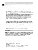
1. Where to install
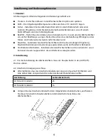
The inverter should be installed in a location that meets the following requirements:
Dry – Do not allow water to drip or splash into the inverter.
Cool – Ambient air temperature should be between -20 and 40 .
℃
℃
Safe – Do not install into a battery compartment or other areas where flammable fumes
may exist, such as fuel storage areas or engine compartments.
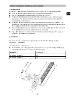
Ventilated – Allow at least one inch of clearance around the inverter for air flow. Ensure
the ventilation openings on the rear and front of the unit are not obstructed.
Dust – Do not install the Inverter in dusty environments. This dust can be pulled into the
unit when the cooling fan is operating.
Away from batteries- Do not mount the Inverter where it will be exposed to corrosive
gases produced by batteries.
2. Installation
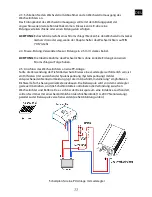
2-1. Before installing the inverter, make sure the main switch is in “OFF” position.
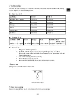
2-2. DC Input connection:
We recommend the DC cable length should be not longer than 6 feet/1.8m, and the
recommended gauge according to below indicated table:
Model No.
Wire (mm
2
)
SI1500-24110/24230
25
SI1500-48110/48230
16
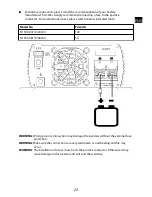
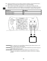
Crimp the DC cable with the ring terminals which are included in the package of the
inverter, then fasten these to the inverter DC connector with a screwdriver.
22
ENG
Summary of Contents for SI1500-24110
Page 70: ...1 2 20 1 3 50 60 Hz LED 68...
Page 74: ...3 2 24 V 48 V 24 V 48 V SI RSW 4 1 2 Vceo 72 TR TR...
Page 75: ...3 4 30 mm 73...
Page 76: ...1 20 40 30 mm 3 m 2 2 1 OFF 2 2 1 8 m SI1500 24110 24230 20 mm2 SI1500 48110 48230 12 mm2 74...
Page 77: ...SI1500 24110 24230 100 A SI1500 48110 48230 50 A 75...
Page 78: ...2 3 2 4 2 5 mm2 2 5 LVD 1 A 200 V 76...
Page 80: ...4 LED 1 6 S 70 5 45 5 12 20120406 Phocos AG www phocos com 78 ISO9001 RoHS...


