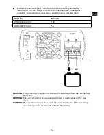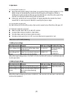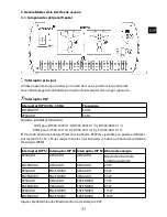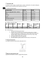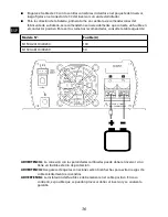
2-3. Plug the AC load plug to the inverter AC outlet.
The AC output ground wire must be connected to the grounding post of your loads ( for
example, a distribution panel ground bus ).
WARNING:
Risk of electronic shock! Never plug the AC plug in or out while the Main switch
in ON position.
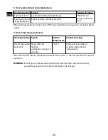
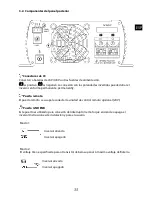
2-4. Chassis Ground: use 2.5mm
2
cable to connect to Ground.
WARNING:
Operation of the inverter without a proper ground connection may result in
electrical shock hazard.
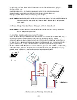
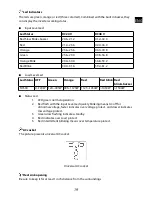
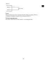
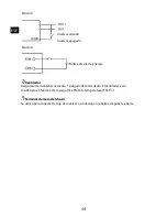
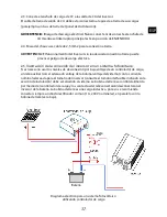
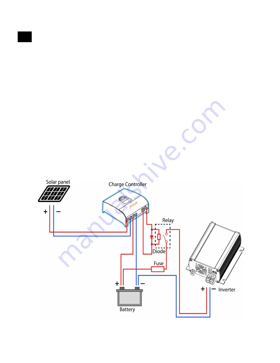
2-5. Use of an External Charge Controller Low Voltage Disconnect (LVD) to control the
Battery Depth of Discharge (DOD):
Should there be a requirement to use the Low Voltage Disconnect levels of a charge
controller, than an auxiliary Relay (with adequate coil voltage/system voltage), with the
proper current rating for the inverter size (refer to the fuse size we indicate in the Installation
section), has to be added to the system. The relay coil will be controlled/powered by the
charge controller and the relay contacts will connect/disconnect the Inverter to/from the
battery. Because the relay coil is an inductive load it is recommended to always connect a
common rectifier type diode (1A, 200V rating), in parallel with the relay coil (see below).
24
ENG
Wiring diagram for a PV system using charge controllers
Summary of Contents for SI1500-24110
Page 70: ...1 2 20 1 3 50 60 Hz LED 68...
Page 74: ...3 2 24 V 48 V 24 V 48 V SI RSW 4 1 2 Vceo 72 TR TR...
Page 75: ...3 4 30 mm 73...
Page 76: ...1 20 40 30 mm 3 m 2 2 1 OFF 2 2 1 8 m SI1500 24110 24230 20 mm2 SI1500 48110 48230 12 mm2 74...
Page 77: ...SI1500 24110 24230 100 A SI1500 48110 48230 50 A 75...
Page 78: ...2 3 2 4 2 5 mm2 2 5 LVD 1 A 200 V 76...
Page 80: ...4 LED 1 6 S 70 5 45 5 12 20120406 Phocos AG www phocos com 78 ISO9001 RoHS...


