background image

Basic information

105555_en_07

PHOENIX CONTACT

7

English

1

Basic information

The portable crimping tool strips conductors in one step and crimps on a ferrule. It crimps 

ferrules in square form. 

The crimping tool is equipped with an inductive sensor which checks the actual conductor 

cross section. If the cross section exceeds or falls below the defined limits, the crimping tool 

does not trigger. The LEDs signal when a cross section is detected as being unsuitable.

In exceptional cases, conductors can be processed although they are not suitable. This 

leads of crimp results that do not conform with the standards.

1.1

Suitable conductors and ferrules

Suitable conductors

The mobile crimping tool is designed to process fine strand class 5 conductors according to 

IEC 60228 with PVC insulation. Only use type H05V-K and H07V-K conductors. Conduc-

tors with very hard insulation such as rubber, silicone, Teflon, and textile insulation are not 

suitable. 

Avoid processing conductors that are very cold (e.g., directly from an unheated ware-

house). The colder the materials to be processed are, the harder and more resistant they 

become. This can lead to increased wear or to mechanical damage.

Please note that the crimping tool can only process a specific conductor cross section. A 

significantly deviating conductor cross section is detected and not processed. It may be 

possible to process similar conductor cross sections, but this could endanger the electrical 

connection. Make sure that conductor cross section and ferrules fit together.

NOTE: To ensure error-free use and the process reliability of the portable crimp-

ing tool, only use the conductors and ferrules described. 

Using unsuitable materials may damage the crimping tool and lead to inferior work results. 

We recommend that you check the quality of the crimp connections every 5000 cycles or 

at the latest after a year.

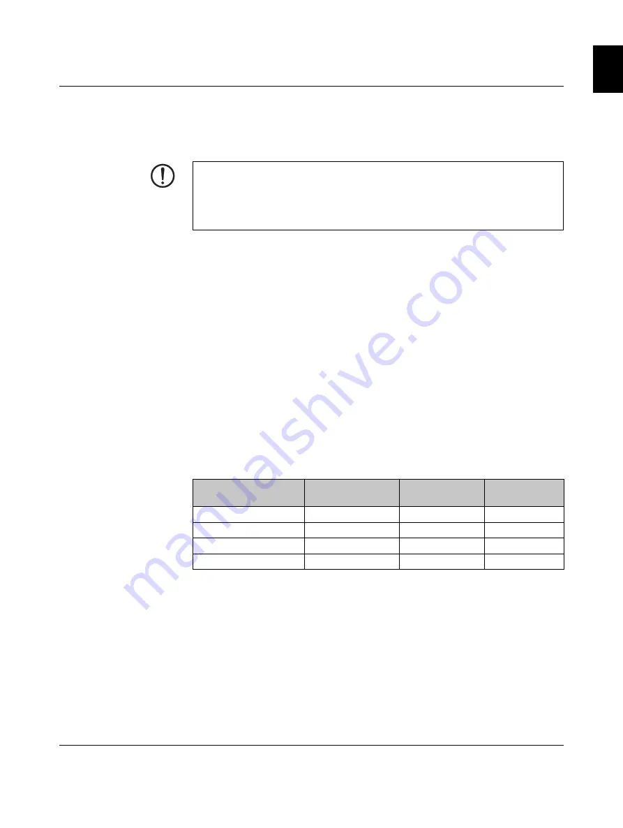
Device type

Conductor cross 

section, metric

Outside diame-

ter

Conductor type

CF CRIMPHANDY 0,5 

0.5 mm²

1.7 mm ... 2.4 mm

H05V-K

CF CRIMPHANDY 0,75 

0.75 mm²

1.9 mm ... 2.6 mm

H05V-K

CF CRIMPHANDY 1,0

1.0 mm²

2.0 mm ... 2.7 mm

H05V-K

CF CRIMPHANDY 1,5

1.5 mm²

2.4 mm ... 3.1 mm

H07V-K 

Summary of Contents for 1212463

Page 1: ...Original operating instructions Operation of the CF CRIMPHANDY portable crimping tool UM EN CF CRIMPHANDY Order No 2910936 ...

Page 2: ......

Page 3: ... portable crimping tool UM EN CF CRIMPHANDY 07 2910936 Designation Order No CF CRIMPHANDY 0 5 1212463 CF CRIMPHANDY 0 75 1212464 CF CRIMPHANDY 1 0 1212465 CF CRIMPHANDY 1 5 1212466 Original operating instructions Designation Revision Order No This user manual is valid for ...

Page 4: ...e 8 32825 Blomberg GERMANY Should you have any suggestions or recommendations for improvement of the contents and layout of our manuals please send your comments to tecdoc phoenixcontact com This is the safety alert symbol It is used to alert you to potential personal injury hazards Obey all safety measures that follow this symbol to avoid possible in jury or death There are three different catego...

Page 5: ...cific application in particular with regard to observ ing the applicable standards and regulations All information made available in the technical data is supplied without any accompanying guarantee whether expressly mentioned im plied or tacitly assumed In general the provisions of the current standard Terms and Conditions of Phoenix Contact apply exclusively in particular as concerns any warrant...

Page 6: ...ed ferrule 15 2 6 Removing the battery 15 3 Troubleshooting 16 3 1 Overview of possible faults 17 3 2 Meaning of the indicator lights 18 3 3 Troubleshooting sequences 19 3 4 Removing the conductor 20 3 5 Removing the ferrule 21 3 6 Relieving blockage at ferrule transport 22 3 7 Removing loose parts 24 3 8 Initializing the crimping tool Reset 26 3 9 Replacing waste guide plates 27 3 9 1 Replacing w...

Page 7: ...conductors that are very cold e g directly from an unheated ware house The colder the materials to be processed are the harder and more resistant they become This can lead to increased wear or to mechanical damage Please note that the crimping tool can only process a specific conductor cross section A significantly deviating conductor cross section is detected and not processed It may be possible ...

Page 8: ...ly Make sure that the conductors are always cut straight Conductors that have been squeezed cut at an angle or already stripped must not be used Even for very short conductors it may happen that they are not crimped correctly Only use cable cutters with sharp blades which cut the conductors and do not squeeze them Do not use diagonal cutters or similar unsuitable tools Quality of the crimping re s...

Page 9: ...s Notes on disposal WARNING Important safety notes for lithium ion batteries Risk of short circuit fire explosion electric shock or damage to health Keep the battery away from metal objects Paper clips coins keys nails and other metal objects that touch the contacts may cause a short circuit Do not submerge the battery in liquids Do not heat or burn the battery Never touch the contact surfaces of ...

Page 10: ...or conductor 2 Indicator lights 3 Reset button The reset button may only be used in the course of trou bleshooting as described in section 3 4 ON button 5 Battery compartment 6 Release button for battery compartment 7 M5 thread for attaching the crimping tool to a balancer 8 Wire check 9 Window for ferrule magazine 10 Flap for opening the ferrule magazine 11 Waste container 12 Service cover wire c...

Page 11: ...ivered Charging the battery Place both pins of the battery in the recesses on the cable side of the charger Press down on the battery at the opposite end Plug the mains plug into the socket During charging the indicator light on the mains plug lights up red It changes to green when the charging process has been completed Inserting the battery in the crimping tool Insert the battery in the battery ...

Page 12: ...y Green on battery full Yellow on battery half full Red on battery almost empty Troubleshooting When the green and red indicator lights flash simultaneously the battery is empty Follow the instructions for charging the battery see Page 11 If the yellow indicator light flashes follow the sequence for in serting a taped ferrule see Page 13 Switching off the crimping tool Press the ON button for appr...

Page 13: ...ht into the guide shaft Then push the taped ferrule to the left as far as it will go into the guide shaft until it engages Closing the lid and attaching the waste container Close the lid When attaching the waste container place it so that it is flush with the lid the waste container will be around five millimeters over the front edge of the crimping tool Push the waste container into the end posit...

Page 14: ...uctor slightly around its own axis The conductor is processed You hear a crimping sound As soon as the conductor is being processed you must not pull or push at it When after approx two seconds the process is concluded pull the conductor out straight When the green indicator light flashes the crimping tool is ready for use again NOTE Damage to the crimping tool Make sure that the conductors are al...

Page 15: ...n and remove the remnants of the tape Please make sure that the remnants of the tape do not fall into the guide shaft Inserting the taped ferrule See Page 13 NOTE Damage to the crimping tool Never remove the battery during the crimping process or troubleshooting The conductor should be taken out before the battery is removed The green and red indicator lights flash simultaneously at short in terva...

Page 16: ...edied using the steps described below Never remove the battery during troubleshooting You may open the service cover to shake out loose parts Do not loosen the screws of the housing to open it This can damage the crimping tool The print DO NOT OPEN on the crimping tool indicates that the crimping tool will be damaged if the housing is opened ...

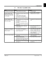
Page 17: ...ions Carefully turn the conductor and pull it out The battery was removed during the crimping process Screw in the service tool and re move the conductor Then initialize device see Page 26 The green and red indicator lights flash slowly but the con ductor is correct The conductor is not recognized The conductor is recognized as having an incorrect cross section Switch off the device without the co...

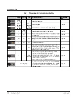
Page 18: ...n ductor Page 20 On On Press the reset button On Check if a ferrule without conductor is stuck in the crimping tool To do so push in the service tool on the plastic side until the red indicator light goes out Then carefully remove the service tool Page 21 Long flashing Open the service cover Remove loose parts from the device and close the service cover again First remove any conductor that is stu...

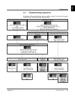
Page 19: ...the tape slide Remove the taped ferrule if present Relieving blockage at ferrule transport Page 22 Removing loose parts Page 24 Press the reset button Press the reset button Open the service cover Remove loose parts Removing the ferrule Page 21 Insert the service tool into the shaft The red indicator light goes out Carefully remove the service tool Ferrule removed Ferrule not removed Close the ser...

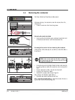
Page 20: ...e crimping tool you will see a bore hole with an inner thread Screw the service tool with the thread into the bore hole as far as it will go Make sure that the service tool is not screwed too tight Now carefully remove the conductor from the shaft Screw out the service tool again Reattach the waste container see Page 13 The yellow and red indicator lights light up Press the reset button with the s...

Page 21: ...indicator light goes out Carefully pull the service tool out straight If there is a ferrule in the crimping die it sticks to the service tool It is possible that no ferrule has been caught The crimping tool detects this and continues with further measures for remedying the fault If the green indicator light flashes the crimping tool is ready If the yellow indicator light flashes no ferrule could b...

Page 22: ...upwards to open There will be slight resistance when doing this Removing the taped ferrule Push the slide towards the front of the device Hold the slide in this position and remove the taped ferrule Always actuate the slide even if no tape was inserted The yellow and red indicator lights light up Press the reset button with the service tool The red indicator light lights up If the red indicator li...

Page 23: ...caught The crimping tool detects this and continues with further measures for remedying the fault The yellow indicator light flashes If the yellow indicator light flashes no ferrule could be removed Follow the sequence for removing loose parts from the device see Page 24 Inserting the taped ferrule Check if the taped ferrule is damaged Detach damaged ferrules from the tape Re insert the taped ferr...

Page 24: ...ferrule Push the slide towards the front of the device Hold the slide in this position and remove the taped ferrule Always actuate the slide even if no tape was inserted The red indicator light flashes Taking off the service cover Loosen the service cover with the service tool For this the service tool has a plastic protrusion that fits in a re cess at the front side of the device With a slight tu...

Page 25: ...age 27 Switching on the crimping tool Reattach the service cover Press the ON button The yellow indicator light flashes If the yellow indicator light lights up follow the sequence for re lieving a blockage see Page 22 Inserting the taped ferrule Check if the taped ferrule is damaged Detach damaged ferrules from the tape Re insert the taped ferrule see Page 13 Reattach the waste container see Page ...

Page 26: ...ze the device Switch off the device Hold the reset button pressed with the service tool Press the ON button as well Release the ON button first Then release the reset button The yellow indicator light lights up Follow the sequence for removing loose parts from the device see Page 24 If this does not work please contact Phoenix Contact ...

Page 27: ...is retrofitted to conform to the current version Checking waste guide plates Check whether the two waste guide plates are undamaged If a waste guide plate is bent you must replace it Ordering data for the upper waste guide plate GP2 CF CRIMPHANDY 0 5 GP2 1212515 CF CRIMPHANDY 0 75 GP2 1212516 CF CRIMPHANDY 1 0 GP2 1212517 CF CRIMPHANDY 1 5 GP2 1212844 Ordering data for the lower waste guide plate ...

Page 28: ...Y GP1 1212514 Check for proper fitting in the slot Re tighten the screw Attaching the service cover Put the service cover on again Loading the taped ferrule Press the ON button You hear a sound of movement and the green indicator light flashes The crimping tool is ready for use If the yellow indicator light flashes insert taped ferrule see Page 13 If the yellow indicator light lights up follow the...

Page 29: ...te with a needle nose pliers Removing residual insulation Check if there is still residual insulation under waste guide plate GP1 Shaking out loose parts Check if there are any loose parts in the device Shake the loose parts out of the device Do not use any tool that could damage the crimping tool Torx 8 NOTE If you screw out the screw too far the crimping tool will be damaged A half turn is suffi...

Page 30: ... button as well Release the ON button first Release the reset button The yellow indicator light lights up Removing the taped ferrule Push the slide towards the front of the device Hold the slide in this position and remove the taped ferrule Always actuate the slide even if no tape was inserted Taking off the service cover Take off the service cover The crimping tool turns off automat ically Attach...

Page 31: ...ate GP2 for your crimping tool Ordering data CF CRIMPHANDY 0 5 GP2 1212515 CF CRIMPHANDY 0 75 GP2 1212516 CF CRIMPHANDY 1 0 GP2 1212517 CF CRIMPHANDY 1 5 GP2 1212844 The small lug must be on the small inclined surface If the lug is pushed behind this surface the new plate will be bent with its first use This lug is indicated in the lower magnifying glass with the single arrow It is important that ...

Page 32: ...waste guide plate in position Retighten the screw Attaching the service cover Put the service cover on again Inserting the taped ferrule Re insert the taped ferrule see Page 13 Reattach the waste receptacle see Page 13 Loading the taped ferrule Press the ON button You hear a sound of movement and the green indicator light flashes The crimping tool is ready for use If the yellow indicator light lig...

Page 33: ... service tool For CF CRIMPHANDY 0 5 CF CRIMPHANDY 0 5 SERVICE TOOL 1212787 1 For CF CRIMPHANDY 0 75 CF CRIMPHANDY 0 75 SERVICE TOOL 1212786 1 For CF CRIMPHANDY 1 0 CF CRIMPHANDY 1 0 SERVICE TOOL 1212759 1 For CF CRIMPHANDY 1 5 CF CRIMPHANDY 1 5 SERVICE TOOL 1212708 1 Replacement waste container for CF CRIMPHANDY CF CRIMPHANDY COVER 1212709 1 Replacement waste guide plate GP1 for CF CRIMPHANDY see ...

Page 34: ... AI 0 5 8 WH S 1212521 color white AI 0 5 8 WH S 1212521 color white AI 0 5 8 OG S 1212784 color orange 0 75 mm for CF CRIMPHANDY 0 75 AI 0 75 8 GY S 1212522 color gray AI 0 75 8 BU S 1212785 color blue AI 0 75 8 WH S 1212783 color white 1 0 mm for CF CRIMPHANDY 1 0 AI 1 0 8 RD S 1212523 color red AI 1 0 8 RD S 1212523 color red AI 1 0 8 YE S 1212782 color yellow 1 5 mm for CF CRIMPHANDY 1 5 AI 1 ...

Page 35: ...h of conductor 32 mm Conductor type H05V K H07V K see table below Insulation type PVC Crimp cycles per battery charge Up to 2000 Ambient temperature operation 15 C 30 C Dimensions W x H x D 43 mm x 205 mm x 70 mm Weight 434 g Noise emission LpA 70 dB A Work cycle trigger Sensor Controller Electrical Indicators Indicator lights LEDs for status indicator Device type Conductor cross section metric Ou...

Page 36: ...CF CRIMPHANDY 36 PHOENIX CONTACT 105555_en_07 ...

Reviews: