5981_en_06
PHOENIX CONTACT
77
A 3.6
Connecting the cables
•
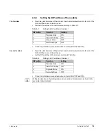
Connect one modem with the RS-232 side of an RS-232/RS-485 converter using a
special 3-position SUB-D9 cable and the SUBCON 9/F-SH connectors (see Table
•
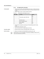
Assemble the adapter cable for the connection between field multiplexer and interface
converter. For the terminal point assignment, please refer to Table A-11.
•
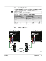
Connect one field multiplexer with the RS-485 side of an RS-232/RS-485 converter.
A wiring example is shown in Figure A-4.
Table A-10
Connection between converter and modem
Converter
PSM-ME-RS232/RS485-P
Modem
PSI-DATA/FAX-MODEM/RS232
Signal
SUBCON 9/F-SH,
Pin
SUBCON 9/F-SH,
Pin
Signal
Shield
Strain relief
Strain relief
Shield
CTS
8
GND
5
5
GND
TxD
3
3
TxD
RxD
2
2
RxD
Jumper pin 8 and
pin 2
ACHTUNG: Malfunction
Please make sure that the cable is not longer than 1 m.
Table A-11
Connection between converter and field multiplexer
Converter
PSM-ME-RS232/RS485-P
field multiplexer
IB IL 24 MUX MA-PAC
Signal
Terminal point
Connector 1,
Terminal point
Signal
Color
Shield
8
1.4 / 2.4
Shield
–
GND
6
1.3
GND
Gray
Data + (B)
2
1.2
Data
Yellow
Data - (A)
1
2.2
/Data
Green
Summary of Contents for 2861205
Page 1: ...User manual Configuring and installing the Inline field multiplexer...
Page 6: ...IB IL 24 MUX MA PAC 6 PHOENIX CONTACT 5981_en_06...
Page 26: ...IB IL 24 MUX MA PAC 26 PHOENIX CONTACT 5981_en_06...
Page 64: ...IB IL 24 MUX MA PAC 64 PHOENIX CONTACT 5981_en_06...
Page 86: ...IB IL 24 MUX MA PAC 86 PHOENIX CONTACT 5981_en_06...


