5981_en_06
PHOENIX CONTACT
81
A 5
Transmission over Ethernet (COM SERVER)
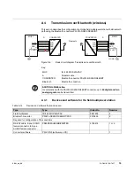
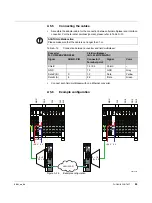
This section describes the configuration of an Inline field multiplexer station with an Ethernet
network path using two Ethernet converters FL COM SERVER RS485.
Figure A-6
Basic circuit diagram: Transmission over Ethernet
Key:
A 5.1
Devices for the field multiplexer station
A 5.2
Basic field multiplexer settings
•
Configure one field multiplexer station as master and the other one as slave (see
Section “Configuring the station as a master or a slave” on page 22).
MUX 1
RS-485
ETH
RS-485
ETH
DATA
GND
DATA
SHD
DATA
D(B)
GND
SHD
D(A)
D(B)
GND
SHD
D(A)
CONVERTER
CONVERTER
A
A
5981A042
MUX 2
DATA
GND
DATA
SHD
DATA
LAN / WAN
MUX
IB IL 24 MUX MA-PAC
A
Adapter cable
CONVERTER
Ethernet converter
For example, Phoenix Contact: FL COM SERVER RS485
LAN/WAN
Ethernet connection
ACHTUNG: Malfunction
In combination with the FL COM SERVER RS485 converter,
a maximum of four analog
signals
can be transmitted.
Table A-14
Devices and software that can be used
Type
Type
Order No.
Number
Field multiplexer
IB IL 24 MUX MA-PAC
2861205
2
Ethernet converter
FL COMSERVER BASIC
2313478
2
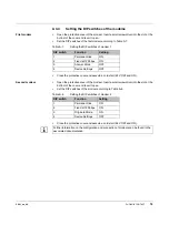
No jumper must
be installed from 1.1 to 2.1 (CONF
FO
) on connector 1 of both field
multiplexers.
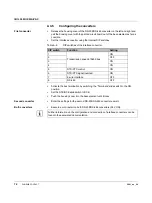
You will find the additional terminal point assignment of the field multiplexer in Section
Summary of Contents for 2861205
Page 1: ...User manual Configuring and installing the Inline field multiplexer...
Page 6: ...IB IL 24 MUX MA PAC 6 PHOENIX CONTACT 5981_en_06...
Page 26: ...IB IL 24 MUX MA PAC 26 PHOENIX CONTACT 5981_en_06...
Page 64: ...IB IL 24 MUX MA PAC 64 PHOENIX CONTACT 5981_en_06...
Page 86: ...IB IL 24 MUX MA PAC 86 PHOENIX CONTACT 5981_en_06...


