QUINT4-PS/1AC/24DC/10
107100_en_01
PHOENIX CONTACT
26 / 50
9.2
Protection of the primary side
Installation of the device must correspond to EN
60950-1
regulations. It must be possible to switch off the device using
a suitable disconnecting device outside the power supply.
The
line protection on the primary side is suitable for this
(see technical data section).
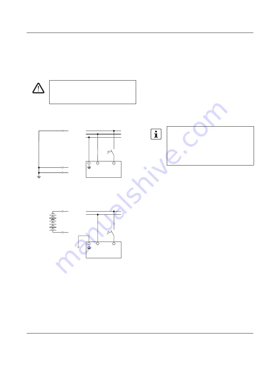
Protection for AC supply
Figure 18
Pin assignment for AC supply voltage
Protection for DC supply
Figure 19
Pin assignment for DC supply voltage
DC applications require upstream installation of a fuse that
is permitted for the operating voltage.
9.3
Output
By default, the power supply is pre-set to a nominal output
voltage of 24
V
DC.
The output voltage is adjusted via the two arrow keys
(-)
and
(+) on the front of the power supply.
When you press the arrow key once briefly, the output
voltage is reduced
(-) or increased
(+) by 3
mV. When you
press the arrow key for longer, the voltage is adjusted in
100
mV increments.
9.4
Protection of the secondary side
The power supply is electronically short-circuit-proof and
no-load-proof. In the event of an error, the output voltage is
limited
DANGER: Hazardous voltage
An all-pos. fuse must be present for operation
on two outer conductors of a three-phase
system.
N/-
L/+
N
PE
L
Input AC 100...240 V
L
N
PE
+
-
PE
N/-
L/+
-
+
Input DC 110...250 V
If sufficiently long connecting cables are used,
fuse protection does not have to be provided
for each individual load.
If each load is protected separately with its
own protective device, the selective shutdown
in the event of a fault enables the system to
remain operational.


