background image

Factory Line - Wireless LAN

3-6

PHOENIX CONTACT

7190_en_02

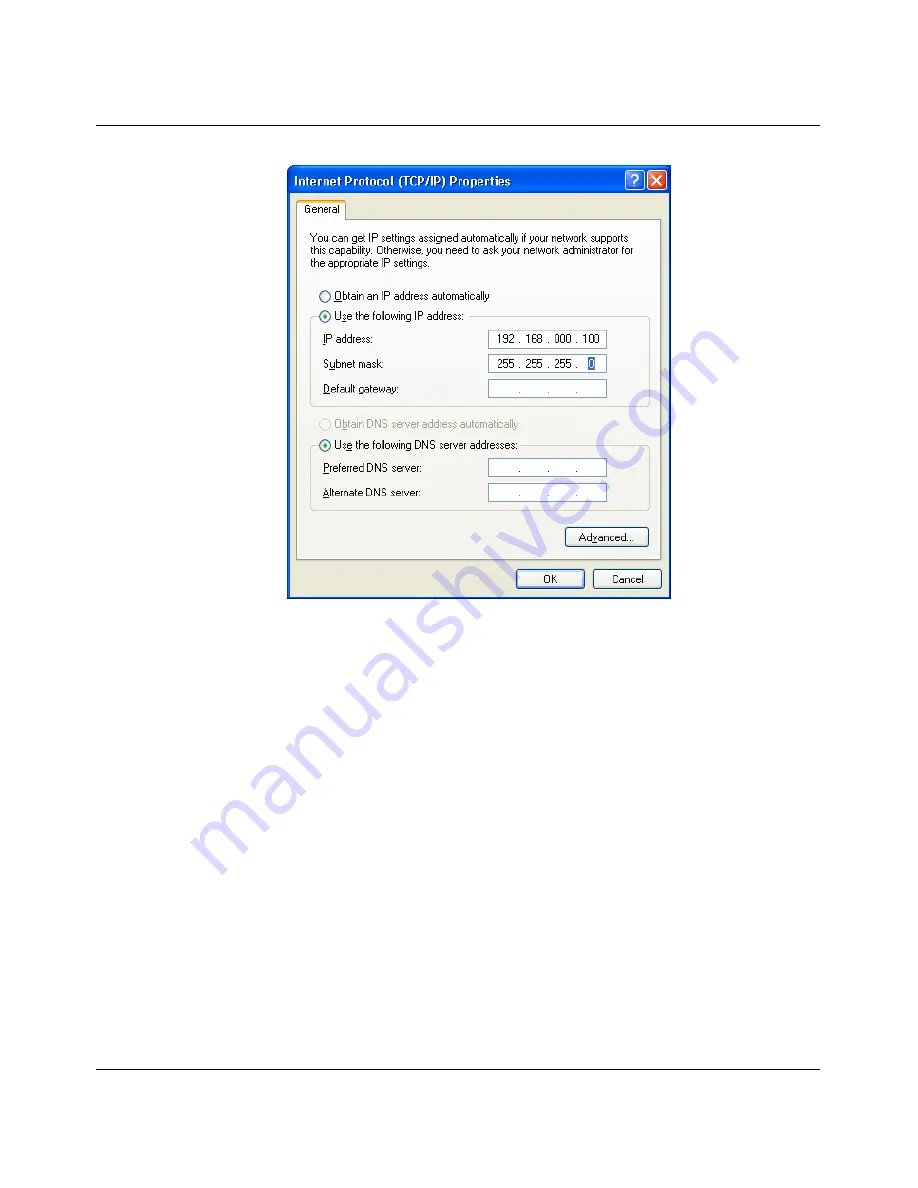
Figure 3-4

Internet Protocol Properties dialog box

Enter the desired IP address in the "IP address" field. The first three bytes of the address 

must be "192.168.0.". The last byte must contain a number between 1 and 253, the value 

"100" is selected in the example. See also 3.5.2.1 "Assigning IP parameters".

"255.255.255.0" must be set as the subnet mask, close the dialog boxes with "OK". 

The device can now be accessed via a web browser. Enter the following address in the 

address line: 

http://192.168.0.254

After the correct user name and password have been entered, the device configuration 

pages are loaded. 

Summary of Contents for FL WLAN 24 AP 802-11

Page 1: ...AUTOMATION UM EN FL WLAN AP EC Order No 28 88 48 2 User manual User manual for the following WLAN devices FL WLAN 24 D AP 802 11 FL WLAN 24 EC 802 11...

Page 2: ......

Page 3: ...2009 AUTOMATIONWORX 7190_en_02 PHOENIX CONTACT For WLAN devices with firmware Version 3 x or later UM DE FL WLAN AP EC 02 28 88 48 2 Designation Order No FL WLAN 24 AP 802 11 28 84 07 5 FL WLAN 24 EC...

Page 4: ...sages provide information about possible property damage and general information concerning proper operation and ease of use This is the safety alert symbol It is used to alert you to potential person...

Page 5: ...rinting errors in the information cannot be ruled out Phoenix Contact does not offer any guarantees as to the reliability accuracy or completeness of the information All information made available in...

Page 6: ...uch rights shall not be excluded How to contact us Internet Up to date information on Phoenix Contact products and our Terms and Conditions can be found on the Internet at www phoenixcontact com Make...

Page 7: ...nd fields of application 2 4 2 2 3 Front view elements 2 4 2 2 4 Housing dimensions 2 6 2 2 5 Status and diagnostic indicators 2 7 2 2 6 Mounting removal 2 7 2 2 7 Mounting the antennas 2 9 2 2 8 Modu...

Page 8: ...ACT 7190_en_02 3 5 3 WLAN device menu 3 32 3 5 4 System menu 3 35 3 5 5 Security in Client mode 3 60 3 6 Example configuration 3 62 4 Technical data 4 1 4 1 Ordering data 4 3 5 Technical appendix 5 1...

Page 9: ...ore The transmission medium is not subject to mechanical wear Mobility and freedom of movement for the devices Large radio fields allow flexible integration of devices independent of the location Brid...

Page 10: ...tromagnetic wave has different dispersion properties depending on its frequency A simple comparison can be made between wave dispersion for Wireless LAN and wave dispersion for visible light Every mat...

Page 11: ...uency and can only be acquired using measuring instruments The unit of attenuation is dB decibel The lower the dB value the lower the attenuation The decibel value indicates the logarithmic relationsh...

Page 12: ...ing the following formula For simple calculations in the 2 4 GHz ISM band the expression 32 4 20 x log 2400 MHz can be replaced by the constant value 100 1 2 3 1 Attenuation due to other effects Radio...

Page 13: ...gure 1 4 Antenna characteristics Table 1 2 Material specific attenuation recommended values Material 2 4 GHz frequency band Rain snow at 50 l m2 per hour 0 02 dB km Fog 0 02 dB km Thin walls 2 to 5 dB...

Page 14: ...r transmission quality at maximum transmission speed depending on the receiver reserve The values are taken from experience and do not take fall back data rates into account the real radio path may de...

Page 15: ...networks Devices that meet this standard are now considered mature and immune to interference and are therefore ideal for professional use in industrial applications Basic specifications for IEEE 802...

Page 16: ...data transmission rate for 802 11a h 5 Mbps to 54 Mbps Net data transmission rate for 802 11a Up to 32 Mbps Net data transmission rate for 802 11h Up to 28 Mbps Band spread method OFDM Orthogonal Fre...

Page 17: ...2 4 GHz ISM band The frequency range includes up to 14 approved channels each with a bandwidth of 22 MHz The channels overlap which means that adjacent channels cannot be used in a wireless network wi...

Page 18: ...nnel access Similar to the CSMA CD method in wired networks in IEEE 802 the CSMA CA Carrier Sense Multiple Access with Collision Avoidance method is specified for channel access in wireless networks T...

Page 19: ...seful when using very long telegrams e g when downloading 1 3 2 Infrastructure mode Basic Service Set Infrastructure mode is the simplest form of a wireless network Communication between all devices i...

Page 20: ...oint is available Active scanning Transmitting a request to all channels If a response is transmitted from an access point it contains all the information required to transfer the communication The de...

Page 21: ...offered the DSSS method at a transmission speed of 11 Mbps This was achieved through the use of the 22 MHz channel but can fall as low as 1 Mbps in unfavorable environmental conditions Spreading the...

Page 22: ...Redundancy With dual access points and Spanning Tree support redundant WLAN structures can be created One wireless interface acts as the access point the other establishes a connection to the adjacen...

Page 23: ...dundancy through the use of Spanning Tree VLAN support according to IEEE 802 1q DHCP client or fixed IP address User interface Password protected access to the web interface Configurable access via HT...

Page 24: ...nel lists roaming thresholds and configurable active scanning Tabular roaming Configurable fixed order of access points e g for linear vehicle systems including Modbus TCP API or SNMP interface for di...

Page 25: ...ng individual parts are supplied as standard One access point client Depending on the item access point dual access point or client two or four antennas for the 2 4 GHz and 5 GHz range Cable feed thro...

Page 26: ...o antennas gain 5 dBi provide diversity so that an optimum radio signal can be achieved even under difficult radio conditions If not stated otherwise all information in this manual is valid for the FL...

Page 27: ...sealed by a sturdy metal cover with five screws Cable feed through The cable feed through consists of rubber grommets with slits in the side which are simply inserted in the cutout provided Status an...

Page 28: ...e 2 4 Housing dimensions of the device in millimeters inches The device is 64 mm 2 520 in deep PWR POE HOST 1 2 3 4 PWR HOST 1 2 3 4 MAC Address FL WLAN 24 AP 802 11 Ord No 28 84 07 5 177 mm 6 693 inc...

Page 29: ...r Ethernet not present HOST right Orange ON Link active OFF Link inactive HOST left Green Flashing Evenly Device in the boot process Erratically Data is being transmitted OFF Device is not in the boot...

Page 30: ...onics module on the mounting plate Attach the electronics module to the mounting plate using two ISO 4017 M4 x 10 8 8 screws These screws do not require additional measures to prevent them from loosen...

Page 31: ...ve it from the mounting plate 2 2 7 Mounting the antennas Two antennas should be mounted for the operation of a WLAN module four antennas should be mounted for a dual access point The supplied antenna...

Page 32: ...er supply unit and Power over Ethernet 2 2 8 1 Connecting the supply voltage 24 V DC Figure 2 7 Connecting the 24 V supply NOTE Electrostatic discharge Observe the necessary safety precautions when ha...

Page 33: ...nding Grounding can be provided in the module wiring space via an eyelet ring that is screwed into the location indicated see Figure 2 7 or the metal surface to which the mounting plate is attached ca...

Page 34: ...tings can be stored on the SIM card not supplied as standard FL WLAN SIM Order No 2692539 Pin assignment 2 2 9 1 Inserting the card in the reader Figure 2 10 Position of the SIM card reader Open the r...

Page 35: ...ore operation is started on this channel The 60 second scan is repeated every 24 hours and results in a connection abort If a radar pulse is detected by an access client during operation this is indic...

Page 36: ...Permissible channels in the 5 GHz frequency range Channel number Frequency in GHz Permitted in 36 5 18 EU USA Japan 40 5 20 EU USA Japan 44 5 22 EU USA Japan 48 5 24 EU USA Japan 52 5 26 EU USA 56 5 2...

Page 37: ...twork authentication Open Encryption Disabled DHCP server Not active DHCP client Active with fall back to static IP address if there is no response to DHCP requests 3 2 2 Reset to default settings The...

Page 38: ...tton 3 2 2 2 Reset via WBM In the Factory Defaults menu click on Reset to Factory Defaults Figure 3 2 Factory Defaults menu 3 3 Making contact for initial configuration As devices are supplied with fi...

Page 39: ...Startup and functions 7190_en_02 PHOENIX CONTACT 3 5 Figure 3 3 Properties dialog box for the network card In the dialog box that opens click on Use the following IP address...

Page 40: ...st byte must contain a number between 1 and 253 the value 100 is selected in the example See also 3 5 2 1 Assigning IP parameters 255 255 255 0 must be set as the subnet mask close the dialog boxes wi...

Page 41: ...il this point the modified configuration is only saved temporarily Only temporarily but not permanently saved modifications are indicated by a flashing floppy disk icon in the top right corner see arr...

Page 42: ...on and Device Information pages provide static information such as information about the device installation the local status and diagnostic indicators or a navigation overview Settings cannot be made...

Page 43: ...Next Figure 3 8 Language selection menu 3 4 1 2 IP configuration The IP configuration defines the host interface response which can be static or automatic Figure 3 9 IP configuration menu Static opti...

Page 44: ...ure is thus replaced by a logical deterministic path with a tree structure without loops using the Spanning Tree algorithm In the event of data path failure some of the previously disconnected connect...

Page 45: ...observed Channel option The device can select the channel automatically or it can be set manually Automatic channel selection Auto is recommended because then the device can switch to another channel...

Page 46: ...In WPA PSK mode a keyword is used in combination with a special encryption method The keyword pre shared key should have a minimum of eight and a maximum of 63 characters It is recommend that you use...

Page 47: ...devices in order to ensure communication Figure 3 13 Selecting the universally supported method WEP 64 bits 128 bits option In WEP 64 128 bits mode as for WPA a keyword is used which enables access to...

Page 48: ...7190_en_02 Next step In the next step the system searches the available frequency spectrum for free channels This process can take a few seconds Figure 3 15 Automatic channel selection If using a dua...

Page 49: ...vice Information main menu in WBM 3 5 1 Device Information menu The Device Information menu contains status information and manufacturer settings for the WLAN AP General Figure 3 16 Device Information...

Page 50: ...IP configuration In the IP configuration menu another IP address can be assigned manually or DHCP can be activated as a mechanism for automatic IP address assignment The Spanning Tree redundancy mech...

Page 51: ...masks are 255 000 000 000 to 255 255 255 252 Default gateway router The IP address of the gateway router must be in the same subnetwork as the address of the device Assigning IP addresses The IP addr...

Page 52: ...ts are available both for the network address network ID and the user address host ID IP addresses can be represented in decimal or hexadecimal form In decimal notation bytes are separated by dots dot...

Page 53: ...d separately using the ping function Value 255 in the byte Value 255 is defined as a broadcast address The telegram is sent to all the computers that are in the same part of the network Examples 004 2...

Page 54: ...k may only contain ones The remaining bits three bytes then contain the address of the subnetwork and the computer The extended IP address is created when the bits of the IP address and the bits of th...

Page 55: ...s differ the packets are forwarded to the router default gateway ANDing the subnet mask and IP address for device 2 System data This menu can be used to enter other important information such as the m...

Page 56: ...which the relevant time offset is applied Enable timeserver option automatic setting of the system time To set the system time automatically server controlled time synchronization an NTP server Netwo...

Page 57: ...apply immediately do not save This function displays an Apply button on all WLAN AP configuration pages which can be used to implement changes immediately To retain the modified configuration after a...

Page 58: ...nu Access control This menu can be used to modify the access method http or https for individual interfaces It is also used to specify whether access violations should be reported via syslog Figure 3...

Page 59: ...an FTP TFTP or HTTP server Figure 3 26 Software update menu 3 5 2 3 Software update procedure 1 Save the desired firmware file to your PC 2 Select the protocol to be used for the update 3 Specify the...

Page 60: ...he address of the computer on which the Factory Manager is installed For Filename and location simply enter the file name of the new firmware file Once the update has been started a new web page is ge...

Page 61: ...sk icon is flashing all the configuration modifications entered since the last permanent save will be lost when the device is switched off To save the active configuration permanently click on Save se...

Page 62: ...on the device The settings from the SIM card are loaded during the boot process and a message is generated in the event log If a configuration is saved to a SIM card from a device with the latest fir...

Page 63: ...Startup and functions 7190_en_02 PHOENIX CONTACT 3 29 Reboot The Reboot menu can be used to trigger a device restart Figure 3 29 Reboot menu...

Page 64: ...to load an available file from your computer to the WLAN device The settings in the file are activated after a device restart Factory defaults The Factory defaults menu can be used to reset the WLAN d...

Page 65: ...very default settings on page 3 3 3 5 3 WLAN device menu 3 5 3 1 WLAN device Status menu The WLAN 1 WLAN 2 and Host menus contain the latest status information The page is updated automatically If the...

Page 66: ...Factory Line Wireless LAN 3 32 PHOENIX CONTACT 7190_en_02 Figure 3 32 Status WLAN menu...

Page 67: ...190_en_02 PHOENIX CONTACT 3 33 Eventlog The event log contains important information about device diagnostics and the system status Device error messages are entered and displayed in the event log Fig...

Page 68: ...e access point A few demo certificates are stored here by default upon delivery Figure 3 34 System Certificate upload menu When a certificate is loaded to the device a validity check is performed auto...

Page 69: ...ns or settings for the interfaces the Enable interface checkbox must be activated Operational mode only for access point This option is used to switch between Access Point and Client mode In Access Po...

Page 70: ...table with regard to interference Regulatory domain Select the country in which the device is operated Only then is it possible to ensure that the various national regulations of the individual countr...

Page 71: ...used The transmission power for antennas in Europe in the 2 4 GHz ISM band is limited to 20 dBm The maximum permissible value that can be entered in WBM is calculated according to the following formul...

Page 72: ...tting which can also be selected in the Filter wizard For 100 compatibility with APs from other manufacturers both MCB and SCB mode can be used Multi Client Bridge This mode enables the operation of t...

Page 73: ...d functions 7190_en_02 PHOENIX CONTACT 3 39 Figure 3 37 Network Bridge mode menu When the dual access point is used Bridge mode can only be modified for WLAN 1 WLAN 2 is always in Fully Transparent Br...

Page 74: ...menu the name server and host name of the device can be configured The name server is used if a host name is used instead of an IP address in a field for the server IP address e g NTP server The host...

Page 75: ...also enables error detection and notification Figure 3 39 Network SNMP menu Select Enable SNMP to activate the SNMP protocol Versions SNMPv1 v2 are unencrypted while SNMPv3 uses user names and passwo...

Page 76: ...which can be used in addition to the user name and password The Generate PSK button can be used to set a randomly generated numerical code which can be used for the PSK Enable SNMP Trap Generation Whe...

Page 77: ...TKIP only CCMP AES only or All If All is selected the devices communicate via the encryption algorithm TKIP The Temporal Key Integrity Protocol describes a security protocol defined in specification...

Page 78: ...N The difference between this and WPA is that the key in WEP is not changed but remains static WEP Wired Equivalent Privacy security mechanisms with 64 bits 128 bits are standard encryption methods ho...

Page 79: ...unication WPA RADIUS In WPA RADIUS mode the access point uses an available RADIUS server for the authentication of user accounts The IP address of the RADIUS server must be entered in the IP address f...

Page 80: ...be used to provide an interface that is configured in the access point with access control The MAC address of a client is then checked against the configurable access list and access may be denied Sin...

Page 81: ...uration of a whitelist is always useful because no clients can then be forgotten during blocking Syslog If this option is selected a message is generated in the event log if a connection attempt is de...

Page 82: ...imum of 500 entries can be stored 3 5 4 7 WLAN device Adv WLAN menu IAPP The Inter Access Point Protocol IAPP is used to exchange control and additional information between access points For example a...

Page 83: ...imarily for fast roaming in order to automatically manage the channel resolution in the 5 GHz band This option is only useful when fast roaming is used Roaming WLAN 1 2 Roaming is always used if a cli...

Page 84: ...also assigned to each MAC address and if this strength is not reached the client changes roams to the next access point in the list Modbus TCP control is available for controlling client roaming which...

Page 85: ...us TCP roaming control Activates the Modbus TCP API of the client A PLC can then request the current position in the roaming list or trigger fast roaming for any entry in the roaming list 3 5 4 9 Modb...

Page 86: ...f 2 bytes each A maximum of 256 stations can be included in the list For a client the value is always 1 Table 3 5 Modbus request for the current number of dialed in stations Request Function code 0x03...

Page 87: ...in WBM The size is two bytes If the client is dialed in to an AP specified in the web interface the number is 0 If the client is not dialed into an AP the number is 0xFF Table 3 9 Modbus request for W...

Page 88: ...ble and is particularly required for 5 GHz with DFS in order to process dynamic channels For 2 4 GHz or for 5 GHz with deactivated DFS the channel for the access point can be fixed The client will the...

Page 89: ...l TPC is to reduce the transmission power of a device as far as possible TPC is always active and cannot be disabled if a 5 GHz channel is used In the 2 4 GHz band TPC is not active by default but can...

Page 90: ...in protocols Figure 3 49 Prioritization WLAN menu The prioritization function is activated by entering a maximum bit rate and at least one priority class For example a maximum bit rate of 50 000 kbps...

Page 91: ...ck that a connected partner can be reached The ping test sends an echo request packet to the destination address of the partner to be checked and evaluates the information from the test Enter the IP a...

Page 92: ...to the appropriate person Action Up down WLAN 1 2 If the Ethernet device can no longer be reached via ICMP this setting switches off the WLAN adapter If ICMP is executed on the gateway of the access...

Page 93: ...IDs can be set Tag option Incoming packets are filtered according to the entered VLAN IDs Outgoing packets are identified with the corresponding VLAN ID Untag option Incoming packets are accepted wit...

Page 94: ...ettings in Client mode 3 5 5 1 Phase 1 Authentication type Set the desired method here EAP TLS EAPTTLS or EAP PEAP User name Enter the relevant user name The user name can be used by the RADIUS server...

Page 95: ...mmon name 3 6 Example configuration The diagram below illustrates a typical application for Wireless LAN It should be possible to address several devices behind the client The table contains the corre...

Page 96: ...d Auto Auto CTS RTS Default Default Fragment threshold Default Default Transmitting antenna Automatic Automatic Transmission power 5 dBi omnidirectional antenna 5 dBi omnidirectional antenna Security...

Page 97: ...ected Weight 1000 g typical Supply voltage Connection Via COMBICON conductor cross section 2 5 mm2 maximum Nominal value 24 V DC Permissible voltage ranges 18 5 V DC to 30 5 V DC Current consumption a...

Page 98: ...1 Mbps Range for 802 11g Outdoors 80 m at 54 Mbps 300 m at 6 Mbps Buildings 15 m at 54 Mbps 35 m at 6 Mbps Impedance 50 Ohm Polarity Vertical horizontal Interfaces continued Filter encryption Filter...

Page 99: ...set for crossed cable 2 pieces FL PLUG RJ45 GN 2 27 44 57 1 Assembly tool for RJ45 connector FL CRIMPTOOL 27 44 86 9 Factory Manager startup diagnostic software FL SWT 28 31 04 4 Network monitoring w...

Page 100: ...Factory Line Wireless LAN 4 4 PHOENIX CONTACT 7190_en_02...

Page 101: ...FROM PXC PRIVATE MIB EnabledDisabledStatus TEXTUAL CONVENTION STATUS current DESCRIPTION This textual convention is used to some variables on the device that only permit two states enableStatus The st...

Page 102: ...nOpMode OBJECT TYPE SYNTAX INTEGER transbridge 1 ACCESS read write STATUS mandatory DESCRIPTION Operational mode of the device When operating as a transparent bridge the device is acting like a layer2...

Page 103: ...S mandatory DESCRIPTION State of this interface It may be enabled or disabled plDevWlanIf1Parameter 1 plDevWlanIf1ParamOpMode OBJECT TYPE SYNTAX OpModeType ACCESS read write STATUS mandatory DESCRIPTI...

Page 104: ...vWlanIf1ParamChannel OBJECT TYPE SYNTAX INTEGER 0 255 ACCESS read write STATUS mandatory DESCRIPTION Channel of this interface This depends on your regional limitations and selected wlanMode 0 means a...

Page 105: ...re secure and faster on station roaming 3 both plDevWlanIf1Security 2 plDevWlanIf1SecWpaPsk OBJECT TYPE SYNTAX OCTET STRING SIZE 8 63 ACCESS read write STATUS mandatory DESCRIPTION Initial key for WPA...

Page 106: ...terface2 params plDevWlanIf2ParamState OBJECT TYPE SYNTAX EnabledDisabledStatus ACCESS read write STATUS mandatory DESCRIPTION State of this interface It may be enabled or disabled plDevWlanIf2Paramet...

Page 107: ...s interface 1 802 11a 2 802 11b 3 802 11b g and 0 802 11a b g for staitons only plDevWlanIf2Parameter 4 plDevWlanIf2ParamChannel OBJECT TYPE SYNTAX INTEGER 1 255 ACCESS read write STATUS mandatory DES...

Page 108: ...ption algorithm 1 TKIP is used on old hardware not supporting AES 2 AES is more secure and faster on station roaming 3 both plDevWlanIf2Security 2 plDevWlanIf2SecWpaPsk OBJECT TYPE SYNTAX OCTET STRING...

Page 109: ...WEP passphrase plDevWlanIf2Security 6 mac filter plDevWlanMacFilter OBJECT IDENTIFIER plDevWlan 40 plDevWlanMacPolicyIf1 OBJECT TYPE SYNTAX INTEGER block 0 allow 1 ACCESS read write STATUS mandatory...

Page 110: ...ccessible STATUS mandatory DESCRIPTION Mac filter table for all wlan interfaces plDevWlanMacFilter 1 plDevWlanMacFilterEntry OBJECT TYPE SYNTAX PlDevWlanMacFilterEntry ACCESS not accessible STATUS man...

Page 111: ...ion OBJECT TYPE SYNTAX INTEGER active 0 inactive 1 disabled 2 ACCESS read write STATUS mandatory DESCRIPTION If this entry is active or inactive plDevWlanMacFilterEntry 3 plDevWlanMacEntryAddress OBJE...

Page 112: ...ryIdx INTEGER plDevWlanIf1FastRoamingEntryThreshold INTEGER plDevWlanIf1FastRoamingEntryChannel INTEGER plDevWlanIf1FastRoamingEntryAddress MacAddress plDevWlanIf1FastRoamingEntryIdx OBJECT TYPE SYNTA...

Page 113: ...PTION Enables the client its Modbus TCP API A PLC may then query the current position in the list or explicitly trigger fast roaming to any position plDevWlanIf1FastRoaming 2 plDevWlanIf1FastRoamToAP...

Page 114: ...R INTEGER plDevWlanIf1StationEntryRate INTEGER plDevWlanIf1StationEntryPower INTEGER plDevWlanIf1StationEntryAddress MacAddress plDevWlanIf1StationEntryIdx OBJECT TYPE SYNTAX INTEGER 0 49 ACCESS not a...

Page 115: ...is station plDevWlanIf1StationsEntry 5 WLAN Stations If2 Table plDevWlanIf2StationsTable OBJECT TYPE SYNTAX SEQUENCE OF PlDevWlanIf2StationsEntry ACCESS not accessible STATUS mandatory DESCRIPTION Tab...

Page 116: ...ationsEntry 1 plDevWlanIf2StationEntrySNR OBJECT TYPE SYNTAX INTEGER 10 60 ACCESS read only STATUS mandatory DESCRIPTION SNR of this station plDevWlanIf2StationsEntry 2 plDevWlanIf2StationEntryRate OB...

Page 117: ...bleAccessPointEntry ACCESS not accessible STATUS mandatory DESCRIPTION An entry conceptual row in the wlanVisibleAccessPointTable INDEX plDevWlanIf1VisibleAccessPointEntryIdx plDevWlanIf1VisibleAccess...

Page 118: ...vWlanIf1VisibleAccessPointEntry 2 plDevWlanIf1VisibleAccessPointEntryChannel OBJECT TYPE SYNTAX INTEGER 0 255 ACCESS read only STATUS mandatory DESCRIPTION TX Rate of this visible access point plDevWl...

Page 119: ...lanIf1VisibleAccessPointEntry 7 plDevWlanIf1VisibleAccessPointEntryConnected OBJECT TYPE SYNTAX INTEGER 0 1 ACCESS read only STATUS mandatory DESCRIPTION SNR of this visible access point plDevWlanIf1V...

Page 120: ...OCTET STRING plDevWlanIf2VisibleAccessPointEntrySecurity OCTET STRING plDevWlanIf2VisibleAccessPointEntryAddress MacAddress plDevWlanIf2VisibleAccessPointEntryConnectedINTEGER plDevWlanIf2VisibleAcces...

Page 121: ...CRIPTION SSID of this visible access point plDevWlanIf2VisibleAccessPointEntry 5 plDevWlanIf2VisibleAccessPointEntrySecurity OBJECT TYPE SYNTAX OCTET STRING ACCESS read only STATUS mandatory DESCRIPTI...

Page 122: ...Factory Line Wireless LAN 5 22 PHOENIX CONTACT 7190_en_02 plDevWlanIf2VisibleAccessPointEntry 8 END...

Reviews: