IB IL 24/230 DOR 4/W-PC (-PAC)
6530B
5
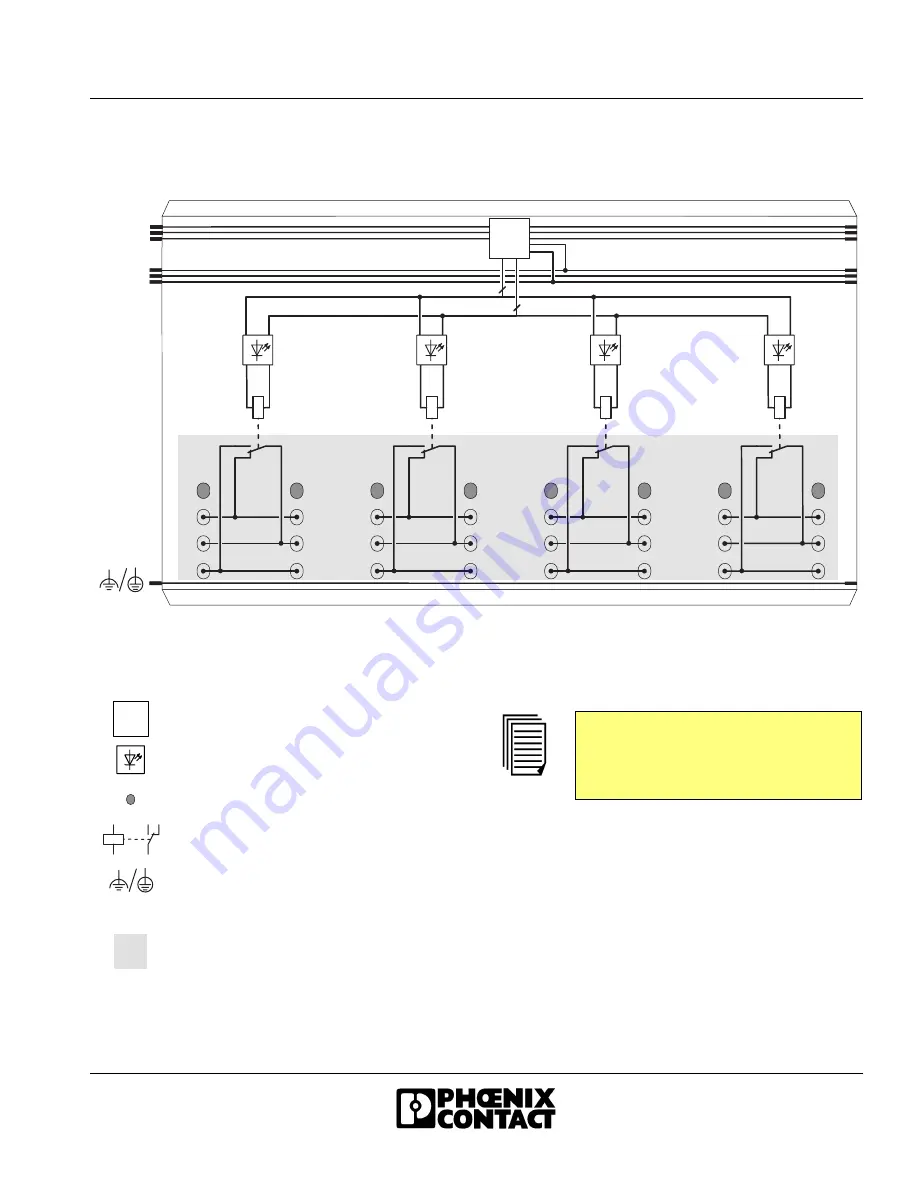
Internal Circuit Diagram
Figure 3
Internal wiring of the terminal points
Key:
L o c a l b u s
U
L
O P C
4
4
6 5 3 0 A 0 0 4
Protocol chip (bus logic including
voltage conditioning)
LED
Terminal point, without metal contact
Relay
FE or PE depending on the area in
which the terminal is used
Electrically isolated area
I/O area including relay contact isolated
from the logic area including the relay
coil through "safe isolation" according
to EN 50178.
O P C
Other symbols are explained in the
IB IL SYS PRO UM E User Manual or in
the Inline System Manual for your bus
system.


