IL PB BK DI8 DO4/EF-PAC
2-8
PHOENIX CONTACT
7725_en_01
Block 6: Status PDU
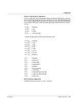
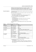
The sixth block is also encoded as a status PDU block, but in manufacturer-specific format.
The information stored here does not usually need to be evaluated.
Byte 5 indicates the baud rate at which the local bus is operated.
Byte 7 and byte 8 indicate the ID and length code of the first faulty terminal. This can be used
as additional information for blocks 2 and 3, if required.
The value of byte 11 is 1 if a system limit was violated.
Byte 12 indicates the number of available terminals.
2.1.2
Status PDU diagnostic format
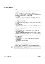
This diagnostic format consists of the following blocks:
1
PROFIBUS standard diagnostics (see also 2.1.1 on page 2-2)
2
Status-PDU (manufacturer-specific)
The bus coupler is always counted as a local bus device (LD). In the event of an error on
the bus coupler, the corresponding bits for local bus device 1 are set in the diagnostics.
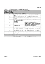
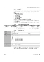
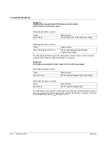
Table 2-7
Status PDU diagnostics incl. error codes
Byte X
Bit 7
Bit 6
Bit 5
Bit 4
Bit 3
Bit 2
Bit 1
Bit 0
Meaning
Block 1
1
X
X
X
X
X
X
X
X
Station status 1
2
X
X
X
X
X
X
X
X
Station status 2
3
X
X
X
X
X
X
X
X
Station status 3
4
X
X
X
X
X
X
X
X
PROFIBUS master address
5
0
0
0
0
1
0
1
1
Manufacturer ID high byte (0B
hex
)
6
0
1
0
1
0
0
0
0
Manufacturer ID low byte (50
hex
)
Block 2
7
0
0
0
0
1
0
0
1
Status (header) + length
8
1
0
1
0
0
0
0
1
Status type = e.g., A1
hex
(header)
9
X
X
X
X
X
X
X
X
Slot number (header)
10
0
0
0
0
0
0
X
X
Status specifier (header)
11
X
X
X
X
X
X
X
X
Error code, high byte
12
X
X
X
X
X
X
X
X
Error code, low byte
13
X
X
X
X
X
X
X
X
User ID code,
local bus device with error
14
X
X
X
X
X
X
X
X
User length code,
local bus device with error
15
X
X
X
X
X
X
X
X
FW version (e.g., 33
hex
)


