Acyclic communication (DP/V1 and PCP)
7725_en_01
PHOENIX CONTACT
3-7
3.4.2
Examples
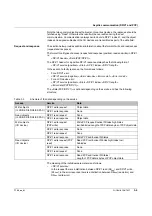
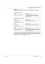
The section below provides a few examples to aid understanding (all values in hex). These
examples indicate how objects on the bus coupler and the I/O devices can be read and
written.
The station structure is as follows:
–
IL PB BK DI8 DO4/EF-PAC
–
IB IL 24 DI8-PAC
–
IB IL AI4/EF-PAC
–
IB IL AO 4/8/U/BP-PAC
–
PD/PCP x words
The IB IL AO 4/8/U/BP and IB IL AI4/EF are capable of PCP.
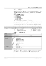
In order to understand the examples, the object dictionary for the IB IL AI4/EF-PAC terminal
should be referred to:
The object dictionary for the IB IL AI4/EF-PAC contains the following object, for example:
Table 3-4
Object dictionary for the IB IL AI4/EF
Table 3-5
Object description:
Objects 4 and 4 on the bus coupler are also used in these examples. For an explanation
regarding these objects, please refer to section "Object dictionaries" on page B-1.
Index
Data type
N
L
Meaning
Object name
Rights
0080
hex
Array of Unsigned 16
6
2
Config Table
rd/wr
N:
Number of elements
rd:
Read access permitted
L:
Length of an element in bytes
wr:
Write access permitted
Object
Config Table
Access
Read, write
Data type
Array of Unsigned 16
6 x 2 bytes
Index
0080
hex
Subindex
00
hex
01
hex
02
hex
03
hex
04
hex
05
hex
06
hex
Write all elements
Configuration of channel 1
Configuration of channel 2
Configuration of channel 3
Configuration of channel 4
Reserved
Reserved
Length (bytes)
0C
hex
02
hex
Subindex 00
hex
Subindex 01
hex
to 06
hex
Data
Terminal configuration

