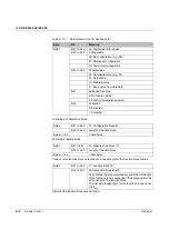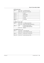
IL PB BK DI8 DO4/EF-PAC
4-8
PHOENIX CONTACT
7725_en_01
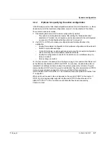
4.3.3
Specifying the active configuration via DP/V0
For DP/V0, the activation status can be accessed via Index 6 or 7. The structure of the
objects differs slightly, therefore typical access is illustrated for both objects.
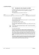
Access via Index 6
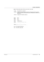
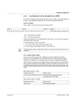
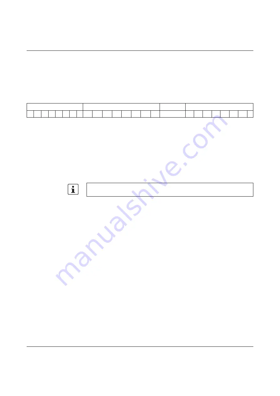
Please observe the structure of index 6 when accessing it:
In this example there are 7 connected terminals. Terminals 1, 2, 3, 4, and 7 should be active.
Terminals 5 and 6 are inactive.
The resulting data for object 6 is as follows:
F2
hex
, 00
hex
, 00
hex
, 00
hex
, 00
hex
, 00
hex
, 00
hex
, 00
hex
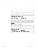
These 8 data bytes are described below as an example for two possible data widths of the
VC1 device.
Two corresponding examples:
If, as described in this example, the configuration and the available terminals differ,
because, e.g., two terminals are not connected, the bus is read in continuously until it is
matches the configuration. The activation status on index 6 is evaluated automatically.
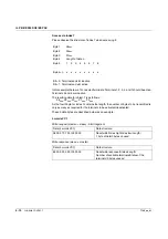
If the active bus configuration is extended and if previously inactive terminals are attached
at the end, these terminals are first activated via index 6. Next time the bus is started, the
new terminals are integrated into the data traffic. The bus can be started via index 4, bit 0.
Please note that during a restart the terminal output data is reset to its terminal-specific reset
values.
If the active bus configuration is extended and previously inactive terminals are attached at
the end, terminal activation and bus restart can be implemented simultaneously via index 7.
The new terminals are integrated into data traffic. Please note that during a restart the
terminal output data is reset to its terminal-specific reset values.
Byte 1
Byte 2
Bytes 3 ... 7
Byte 8
1
2
3
4
5
6
7
8
9
10
11
12
13
14
15
16
...
57
58
59
60
61
62
63
x
Bit = 0: Terminals and slot inactive
Bit = 1: Terminals and slot active
If a new activation status is described via index 6 or index 7, it only becomes valid when
the bus is restarted.

