IO-Link
7725_en_01
PHOENIX CONTACT
6-1
6
IO-Link
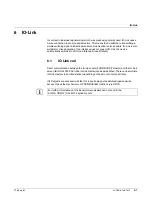
In contrast to individual signal wiring, which was previously primarily used, IO-Link uses a
3-wire connection to sensors and actuators. This means that in addition to transmitting a
simple switching signal, bidirectional serial communication is also possible. IO-Link is also
suitable for mixed operation. If an interface does not support IO-Link, the device
automatically switches to SIO mode (Standard Input/Output).
6.1
IO-Link call
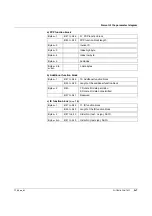
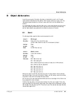
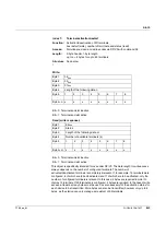
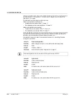
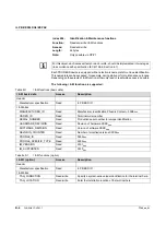
Direct communication between the IO-Link client (PROFIBUS DP master) and the IO-Link
server (IB IL IOL4 DI2-PAC Inline IO-Link master) can be established. There can be multiple
IO-Link masters in an Inline station (depending on the amount of process data).
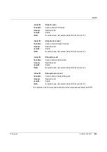
IOLD objects are accessed with the IO-Link call being a standardized read and write
access. It uses the mechanisms of PROFIBUS I&M functions (via DP/V1).
For further information on IO-Link call communication can be found in the
AH FLS PB M12 IOL 4 M12 application note.

