


5756B
7
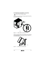
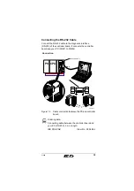
been designed as a 9-pos. D-SUB male connector. The board
is connected to the PC with the RS-232 cable IBS PRG CAB
(Order No. 28 06 86 2) shown below.
Figure 3
Diagnostic interface and RS-232 cable
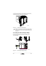
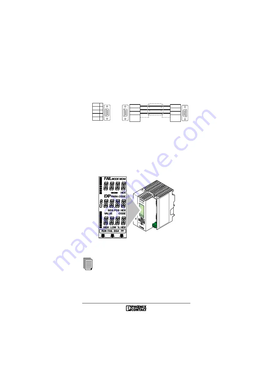
Diagnostic Indicators
The LCD is used to indicate operating and error states of the
controller board. For further information about the indicators
on the display and their meanings, please refer to the back
cover of this guide.
Figure 4
Diagnostic display with representation of the
individual segments and lines
For further information about error messages, please
refer to the IBS SYS DIAG DSC UM E Diagnostics
Guide.
R S - 2 3 2 c a b l e
9 - p o s . D - S U B
f e m a l e c o n n e c t o r
S o l d e r
s i d e
6
9
1
5
S o l d e r
s i d e
9 - p o s . D - S U B
f e m a l e c o n n e c t o r
9
6
5
1
9 - p o s . D - S U B
m a l e c o n n e c t o r
M a l e
s i d e
G N D
R X D
T X D
R T S
C T S
2
3
5
7
8
6
9
1
5
D i a g n o s t i c i n t e r f a c e
5 7 5 6 A 0 0 4
S t r a i n
r e l i e f
5
2
3
S t r a i n
r e l i e f
5
2
3
5 7 5 6 A 0 0 5
S T O P
7
6
5
4
3
2
1
0
7
6
5
4
3
2
1
0


