44
5756B
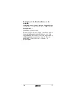
Description of the Diagnostic Registers
The diagnostic display is mapped to the PLC by the
diagnostic status register and diagnostic parameter register.
These registers inform the PLC about the current state of the
INTERBUS system. In the application program, operating
states, errors, and other information are represented as
inputs.
The extended diagnostic parameter register contains
additional diagnostic information about the INTERBUS
system (e.g., Inline devices). In case of error this register is
mapped using the diagnostic function FC 24 in DBW 168 of
the IBDB.
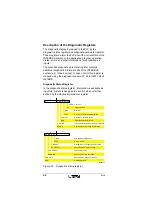
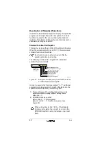
Diagnostic Status Register
In the diagnostic status register, information is available as
input bits. A state is assigned to each bit, which is further
defined by the diagnostic parameter register.
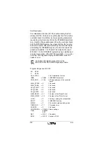
Figure 30
Diagnostic status register
n + 1
W A R N I N G
S D S I
S Y - R E S U L T
C P U i n S T O P
S y n c h r o n i z a t i o n e r r o r o c c u r r e d
S p e c i f i e d w a i t t i m e e x c e e d e d
M e s s a g e f o r P L C
B S A
B u s s e g m e n t s w i t c h e d o f f
R E S U L T
S t a n d a r d f u n c t i o n n e g a t i v e l y p r o c e s s e d
D C - R E S U L T
F a u l t y d a t a c y c l e s
Q U A L I T Y
S p e c i f i e d e r r o r d e n s i t y e x c e e d e d
S T O P
7 6 5 4 3 2 1 0
7
0
n
n + 1
R U N
R E A D Y
C T R L
P e r i p h e r a l f a u l t
E r r o r o n c o n t r o l l e r b o a r d / h a r d w a r e
D a t a t r a n s m i s s i o n i s a c t i v e
C o n t r o l l e r b o a r d i s r e a d y f o r o p e r a t i o n
U S E R
U s e r e r r o r
B U S
B u s e r r o r
D E T E C T
D i a g n o s t i c r o u t i n e i s a c t i v e
A C T I V E
S e l e c t e d c o n f i g u r a t i o n i s r e a d y f o r o p e r a t i o n
P F
7 6 5 4 3 2 1 0
7
0
n
5 7 5 6 B 0 4 5

