RAD-ISM-900-EN-BD…
5-24
PHOENIX CONTACT
2476_en_I
5.6.6
Digital Pulse Input Module
The Digital Pulse Input Module accepts pulse signals from many different types of devices.
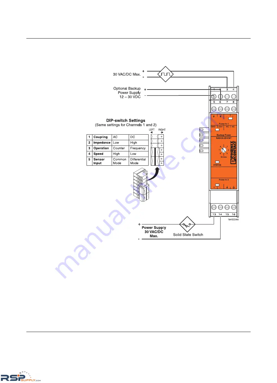
Figure 5-10
RAD-IN-2D-CNT Pulse Input Module wire diagram
Backup Power
The Digital Pulse Input Module will retain its pulse count if power is removed; however, it will
not record any new pulses. Terminals 5 and 6 are used for connecting the backup power
supply to the module. If primary power (through the bus connector from the radio) is lost, the
backup power supply allows the module to continue to record pulses. The backup power
terminals will not supply power to the transceiver or any other module on the bus connector.
DIP Switch Settings
Refer to Figure 5-9 on page 5-23 for DIP switch configurations.
RSPSupply - 1-888-532-2706 - www.RSPSupply.com
http://www.RSPSupply.com/p-12970-Phoenix-Contact-2900016-Radio-900-MHz-Ethernet-Radio.aspx


