background image

© PHOENIX CONTACT - 12/2005

Data Sheet

INTERFACE

100028_04_en

1

PHOENIX CONTACT GmbH & Co. KG • 32823 Blomberg • Germany

Phone: +49 - 52 35 - 30 0 • Fax: +49 - 52 35 - 34 12 00 • www.phoenixcontact.com

www.phoenixcontact.com/salesnetwork

QUINT-PS-100-240AC/24DC/2.5

Description

QUINT POWER devices are 60...960 W DC power supply 
units for universal use. This is ensured by the wide-range 
input, single and three-phase versions, and an international 
approval package. 

QUINT POWER stands for guaranteed supply: powerful 
capacitors ensure mains buffering of more than 20 ms at full 
load. 

All three-phase devices provide the full output power, even 
in the event of a continuous phase failure. 
The POWER BOOST power reserve starts loads with high 
inrush currents and ensures that fuses are reliably tripped. 

Preventive function monitoring diagnoses impermissible 
operating states and minimizes downtimes in your system. 
An active transistor output and a floating relay contact are 
used for remote monitoring. 

All QUINT POWER devices are idling-proof and 
short-circuit proof, and are available with a regulated and 
adjustable output voltage of 12, 24, and 48 V DC with output 
currents of 2.5, 5, 10, 20, 30, and 40 A. 

Power supply units for use in Ex Zone 2, uninterruptible 
solutions, AS-i power supply units, and a QUINT diode 
complete the product range.

QUINT POWER is a built-in device. Installation 
and startup must only be carried out by 
qualified personnel. The relevant country-
specific regulations (e.g., VDE, DIN) must also 
be observed.

Danger
The device contains dangerous live elements and high levels of stored energy.
Never carry out work when the power is turned on. 

Risk of burns
The housing temperature can reach high values depending on the ambient temperature and the load of the 
device. 

Make sure you always use the latest documentation. 
It can be downloaded at 

www.download.phoenixcontact.com

.

A conversion table is available on the Internet at

www.download.phoenixcontact.com/general/7000_en_00.pdf

.

This data sheet is valid for all products listed on the following page:

Single-Phase Primary-Switched Power Supply Unit

Summary of Contents for QUINT-PS-100-240AC/24DC/2.5

Page 1: ...are used for remote monitoring All QUINT POWER devices are idling proof and short circuit proof and are available with a regulated and adjustable output voltage of 12 24 and 48 V DC with output curren...

Page 2: ...A or 16 A Characteristic B Discharge current to PE 3 5 mA Connection method COMBICON screw plug in connection Stripping length 7 mm Output Data Nominal output voltage 24 V DC 1 Setting range for the o...

Page 3: ...ration 95 at 25 C no condensation Vibration operation 15 Hz amplitude 2 5 mm according to IEC 60068 2 6 15 150 Hz 2 3g 90 minutes Shock 30g in all space directions according to IEC 60068 2 27 Pollutio...

Page 4: ...l Cable to ground 0 5 kV Level 1 symmetrical Cable to cable 1 kV Level 1 asymmetrical Cable to ground Surge current load surge EN 61000 4 5 Criterion B2 Input Output Signal 4 kV Level 4 asymmetrical 2...

Page 5: ...he relevant country specific regulations e g VDE DIN must also be observed Before startup please ensure The mains has been connected correctly and protection is provided against electric shock The dev...

Page 6: ...g position Installation depth 58 mm DIN rail Narrow Mounting Position Default Upon Delivery Figure 5 Narrow mounting position Assembly Position the module with the DIN rail guideway on the top edge of...

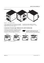
Page 7: ...Torx T10 torque 0 8 0 9 Nm Connection of Various Types of Network 100 240 V AC Networks The device can be connected to single phase AC networks or to two external conductors for three phase networks...

Page 8: ...ded Backup Fuse Circuit breaker 6 A 10 A or 16 A Characteristic B or equivalent Protecting the Primary Side The device must be installed according to the specifications of EN 60950 Connectors may only...

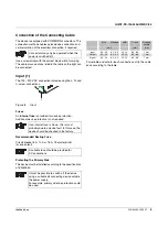
Page 9: ...ximum of 1 A can be switched Active Signal Output Figure 11 Active signal output The 24 V DC signal is between the DC OK and connection terminal blocks and can be loaded with 40 mA maximum This signal...

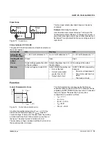
Page 10: ...to IBOOST The secondary voltage is reduced until the short circuit on the secondary side is removed The U I characteristic curve ensures that both heavy capacitive loads and loads with DC DC converte...

Page 11: ...ndant circuits are suitable for supplying systems which place particularly high demands on operational safety If a fault occurs in the primary circuit of the first power supply unit the second device...

Reviews: