background image

QUINT4-PS/3AC/24DC/10

107104_en_01

PHOENIX CONTACT

11 / 51

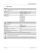
Ambient conditions

Ambient temperature (operation)

-25 °C ... 70 °C (> 60 °C Derating: 2.5 %/K)

The ambient temperature (operation) refers to UL 508 surrounding air temperature.

Ambient temperature (start-up type tested)

-40 °C

Ambient temperature (storage/transport)

-40 °C ... 85 °C

Max. permissible relative humidity (operation)

 95 % (at 25 °C, non-condensing)

Installation height

 5000 m (> 2000 m, observe derating)

Vibration (operation)

5


Hz ... 100


Hz resonance search 2.3g, 90


min., resonance 

frequency 2.3g, 90


min. (according to DNV GL Class C)

Shock

18 ms, 30g, in each space direction (according to IEC 60068-

2-27)

Degree of pollution

2

Climatic class

3K3 (in acc. with EN 60721)

Overvoltage category

EN 60950-1

EN 61010-1

EN 62477-1

II (

 5000


m)

II


(

≤ 

5000


m)

III


(

≤ 

2000


m)

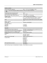
Standards

Safety transformers for power supply units

EN 61558-2-16 (air clearances and creepage distances only)

Electrical safety (of information technology equipment)

IEC


60950-1/VDE


0805 (SELV)

Electrical safety (of control and regulation devices)

IEC 61010-1

Electronic equipment for use in electrical power 

installations

EN 50178/VDE 0160 (PELV)

SELV

IEC


60950-1 (SELV)

EN 60204-1 (PELV)

Network version/undervoltage

SEMI F47-0706; EN 61000-4-11

Rail applications

EN


50121-3-2

EN 50121-4

EN 50121-5

IEC 62236-3-2

IEC 62236-4

IEC 62236-5

EMC requirements, power plant

IEC


61850-3

EN


61000-6-5

HART FSK Physical Layer Test Specification Compliance Output voltage U

Out

 compliant

Summary of Contents for QUINT4-PS/3AC/24DC/10

Page 1: ...ort form Input voltage range 3x 400 V AC 500 V AC 20 10 2x 400 V AC 500 V AC 10 10 Mains buffering 22 ms 3x 400 V AC 22 ms 3x 480 V AC Nominal output voltage UN 24 V DC Setting range of the output vol...

Page 2: ...a 5 5 Safety and installation notes 17 6 High voltage test HIPOT 18 7 Structure of the power supply 20 8 Mounting removing the power supply 23 9 Device connection terminal blocks 26 10 Output characte...

Page 3: ...he wireless configuration of NFC capable products from PHOENIX CONTACT with software No separate USB driver is required TWN4 MIFARE NFC USB ADAPTER 2909681 1 Fuse for the photovoltaics industry accord...

Page 4: ...channel electronic device circuit breaker with active current limitation for protecting four loads at 24 V DC in the event of overload and short circuit With nominal current assistant and electronic l...

Page 5: ...mption apply for 3AC operation in static boost and 2AC operation at nominal power Discharge current to PE typical 3 5 mA 1 mA 550 V AC 60 Hz Mains buffering 22 ms 3x 400 V AC 22 ms 3x 480 V AC Switch...

Page 6: ...cted externally upstream Choice of suitable circuit breakers 1x 6 A 10 x 38 mm 30 kA L R 2 ms 1000 V DC Electric strength of the insulation A B C D Type test IEC EN 60950 1 3 5 kV AC 4 kV AC 0 5 kV DC...

Page 7: ...00 1 25 0 2 4 8 12 16 20 I A Out I A In 6 10 14 18 U 400 V 3AC U 24 V DC In Out U 480 V 3AC U 24 V DC In Out Input connection data Connection method Screw connection Conductor cross section solid 0 2...

Page 8: ...es yes Feedback resistance 35 V DC Protection against surge voltage on the output 32 V DC Rise time typical 1 s UOut 10 90 Output connection data Connection method Screw connection Conductor cross sec...

Page 9: ...nductor cross section flexible 0 2 mm 1 5 mm Conductor cross section flexible with ferrule with plastic sleeve 0 2 mm 0 75 mm Conductor cross section flexible with ferrule without plastic sleeve 0 2 m...

Page 10: ...0 Side element version Aluminum Hood version Stainless steel X6Cr17 Dimensions W H D state of delivery 50 mm 130 mm 125 mm Dimensions W H D 90 turned 122 mm 130 mm 53 mm Weight 0 9 kg Power dissipatio...

Page 11: ...27 Degree of pollution 2 Climatic class 3K3 in acc with EN 60721 Overvoltage category EN 60950 1 EN 61010 1 EN 62477 1 II 5000 m II 5000 m III 2000 m Standards Safety transformers for power supply un...

Page 12: ...12 51 Approvals UL UL Listed UL 508 UL C UL Recognized UL 60950 1 UL ANSI ISA 12 12 01 Class I Division 2 Groups A B C D Hazardous Location CSA CAN CSA C22 2 No 60950 1 07 CSA C22 2 No 107 1 01 SIQ B...

Page 13: ...ntial EN 61000 6 2 industrial and EN 61000 6 5 power station equipment zone IEC EN 61850 3 energy supply CE basic standard Minimum normative requirements of EN 61000 6 2 CE immunity for industrial env...

Page 14: ...8 50 Hz 60 Hz 30 A m 16 7 Hz 50 Hz 60 Hz 100 A m 60 s not required 50 Hz 60 Hz 1 kA m 3 s not required 0 Hz 300 A m DC 60 s Comments Criterion A Criterion A Voltage dips EN 61000 4 11 Input voltage 4...

Page 15: ...ce variables EN 61000 4 16 Input Output Signals 15 Hz 150 Hz 10 V on 1 V 150 Hz 1 5 kHz 1 V 1 5 kHz 15 kHz 1 V on 10 V 15 kHz 150 kHz 10 V Test Level 3 15 Hz 150 Hz 30 V on 3 V 150 Hz 1 5 kHz 3 V 1 5...

Page 16: ...vior within the specified limits Criterion B Temporary impairment to operational behavior that is corrected by the device itself Criterion C Temporary adverse effects on the operating behavior which t...

Page 17: ...nvironment The power supply is mounted in a control cabinet For the connection parameters for wiring the power supply such as the required stripping length with and without ferrule refer to the techni...

Page 18: ...ltage testing is performed as part of the safety approval process type test and manufacturing routine test 6 2 High voltage dielectric test during the manufacturing process During the manufacturing pr...

Page 19: ...ng please reconnect the gas filled surge arrester Figure 2 Disconnect gas filled surge arrester To disconnect the gas filled surge arrester proceed as follows 1 Remove power from the unit 2 Unscrew th...

Page 20: ...cable binders 3 Signaling connection terminal blocks 4 Status and diagnostics indicators 5 NFC interface Near Field Communication 6 AC input voltage connection terminal blocks 7 Gas filled surge arre...

Page 21: ...s in mm Nominal output capacity Spacing mm a b c 50 0 40 20 50 5 50 50 If adjacent components are active and the nominal output power 50 there must be lateral spacing of 15 mm b 130 50 NFC QUINT POWER...

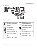
Page 22: ...on Power factor correction PFC Switching transistor and main transmitter electrically isolating Secondary rectification and smoothing Filter Auxiliary converter electrically isolating active PFC Inrus...

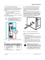
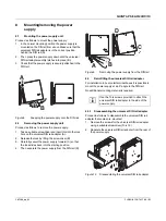
Page 23: ...2 Release the lock by lifting the screwdriver B 3 Carefully swivel the power supply forward C so that the lock slides back into the starting position 4 Then separate the power supply from the DIN rai...

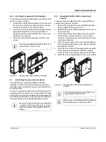
Page 24: ...l of mechanical stability is ensured 8 4 1 Mounting the UWA 182 52 universal wall adapter Proceed as follows to disassemble the universal DIN rail adapter that comes pre mounted 1 Remove the screws fo...

Page 25: ...13 Mounting the UWA 130 universal wall adapter 8 5 Fix connection wiring to the power supply Two receptacles for the bundled attachment of the connection wiring are integrated in the left and right ho...

Page 26: ...inal blocks Figure 17 Network configurations in star network NOTE Mechanical damage to the connection wiring caused by friction In extreme ambient conditions e g strong vibrations protect the connecti...

Page 27: ...t of the power supply When you press the arrow key once briefly the output voltage is reduced or increased by 3 mV When you press the arrow key for longer the voltage is adjusted in 100 mV increments...

Page 28: ...for the application Not suitable for the application Symbol Designation Characteristics Your benefits Reliable power supply A stable 24 V even in the event of a sustained overload No over dimensioned...

Page 29: ...of loads The power supply operates in the nominal operating range Energy supply to the load is ensured Figure 20 U I Advanced output characteristic curve 10 2 Smart HICCUP output characteristic curve...

Page 30: ...threshold and the time period for which it may be exceeded can be freely selected The power supply is restarted via the remote contact As an option the power supply can be switched on by switching th...

Page 31: ...ccessfully installed 11 2 Configuring the power supply To configure the power supply proceed as follows Before you can configure the power supply it should either be disconnected from the supply volta...

Page 32: ...load supply with up to 125 of the nominal current of the power supply The static boost is available at an ambient temperature of up to 40 C Figure 25 Performance characteristic in static boost 12 2 D...

Page 33: ...very time tPause of 2 4 s the dynamic boost is available once again Figure 29 Example recovery time for 40 C If a current that is lower than the maximum available dynamic boost current IDyn Boost is r...

Page 34: ...is tripped by the high SFB current of the power supply typically within 3 to 5 ms As a result voltage dips at loads that are connected in parallel are avoided Figure 30 SFB pulse trips circuit breake...

Page 35: ...Maximum distance l m with device circuit breaker Conductor cross section A mm 0 75 1 0 1 5 2 5 AWG 18 17 16 14 Phoenix Contact CB TM1 1A SFB P 27 36 54 91 CB TM1 2A SFB P 18 25 37 63 CB TM1 3A SFB P 1...

Page 36: ...6 46 62 93 156 C2 42 57 85 143 C3 33 44 66 110 C4 24 33 49 82 C6 15 20 30 51 B6 5 7 11 18 C1 3 4 6 11 C1 6 7 10 15 25 C2 4 6 9 15 C3 3 4 7 11 Tripping magnetic DC correction factor 0 Hz Siemens 1 4 AB...

Page 37: ...2A 3 1 19 25 38 63 GMA 2 5A 4 9 12 16 25 42 GMA 3 15A 4 9 7 9 14 23 GMA 3 5A 9 7 6 8 12 21 GMA 3 5A 13 4 6 9 16 GMC 1A 1 8 23 31 47 78 GMC 1 25A 3 4 17 22 34 56 GMC 1 5A 5 4 10 14 21 36 GMC 1 6A 5 8 1...

Page 38: ...side using the QUINT POWER software or the QUINT POWER app Upon delivery the power supply is pre allocated a default configuration for the signal outputs 14 1 Location and function of the signaling el...

Page 39: ...ut 1 indicates that the set output voltage has been undershot by more than 10 UOUT 0 9 x UN In the default configuration the signal output Out 2 indicates that the nominal power has been exceeded The...

Page 40: ...INT POWER default settings upon delivery Out 1 digital 0 24 V DC 20 mA Out 2 digital 0 24 V DC 20 mA Relay 13 14 floating 24 V DC 1 A 30 V AC 0 5 A Out 2 analog 4 20 mA Output voltage 25 135 90 Defaul...

Page 41: ...t fan or cooling system fails In the event of any form of overtemperature the power supply provides a warning by means of this signal well before the supply of the loads is in any danger Specification...

Page 42: ...upply to SLEEP MODE Figure 38 External wiring versions with PNP and NPN output 14 5 LED status indicators Four LED status indicators are integrated in the front of the power supply which indicate the...

Page 43: ...D DC OK LED P 100 Out Signal Out 2 P P Out N Relay 13 14 DC OK LED P 50 Out Default Default P P Out N U 0 9 x U Out Set Signal Out 1 DC OK LED P 75 Out Active High Active High Active High Active Low A...

Page 44: ...9 SLEEP MODE signaling In SLEEP MODE all LEDs are off all signals are low and the relay switching contact is open LED DC OK LED P 100 Out Signal Out 2 P P Out N Relay 13 14 DC OK LED P 50 Out Default...

Page 45: ...using signals in accordance with EN 62236 4 and EN 50121 4 When using the digital signals a relay Phoenix Contact Order No 2900299 or a comparable relay can be implemented 14 10 3 Surge protection fo...

Page 46: ...chematic diagram in parallel operation Observe the following points when carrying out parallel connection 1 Use power supplies of the same type and performance class 2 Setting the same output voltages...

Page 47: ...with the QUINT ORING or QUINT S ORING active redundancy module Figure 46 Schematic diagram redundant operation with QUINT ORING Figure 47 Schematic diagram redundant operation with QUINT S ORING Certa...

Page 48: ...g a load on the affected phase as in the case of a cooling unit sustained operation on two phases is possible This type of scenario is already covered for QUINT POWER by virtue of its approval Figure...

Page 49: ...sed on the prevailing ambient temperature The recommended output power for different mounting positions and ambient temperatures can be found in the characteristic curves below Exceeding these values...

Page 50: ...0 B o o s t 7 5 5 0 D C O K U Ou t 2 9 5 V 2 4 V 1 3 1 4 R e m S G n d O u t 1 O u t 2 S ig n a l T C 0 25 50 75 100 125 150 175 200 225 25 0 10 20 30 40 50 60 70 P 125 Stat PN 100 PDyn 200 P Out Z X...

Page 51: ...ed mounting position 270 X axis Z X Y T C 0 25 50 75 100 125 150 175 200 225 25 0 10 20 30 40 50 60 70 P 125 Stat PN 100 PDyn 200 P Out Z X Y M3x8 N F C 1 0 0 B o o s t 7 5 5 0 P o u t 1 3 1 4 R e m S...

Reviews: