SD FLASH 512MB MODULAR MUX
18 / 56
PHOENIX CONTACT
105752_en_03
Figure 3
-
11
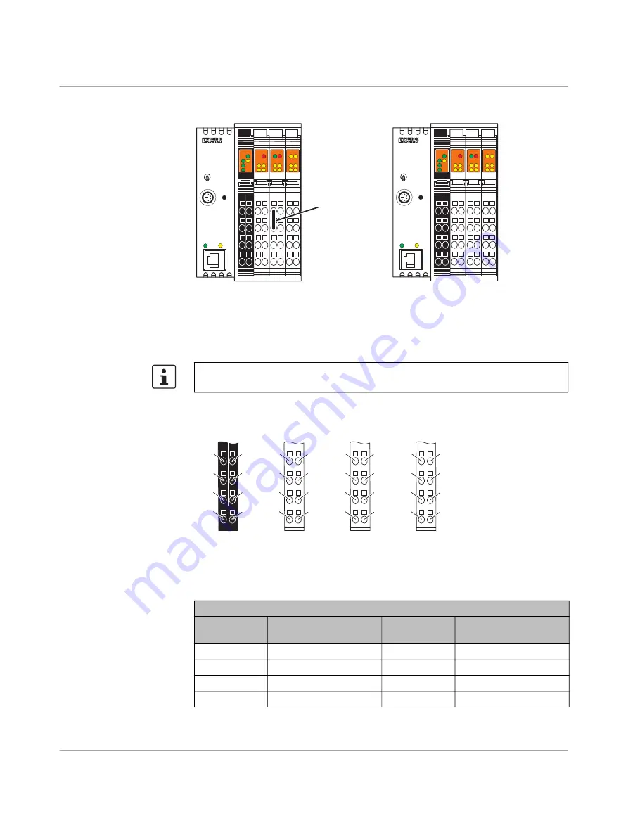
Configuring the Inline controllers as master and slave
Connection assignment of the supply, actuators and sensors
Figure 3
-
12
Terminal points of Inline connectors
The digital inputs are only used for configuration purposes, they are not available as
I/O ports.
Power connector 1, PWR
Terminal
point
Assignment
Terminal
point
Assignment
1.1
U
S
2.1
U
M
1.2
U
L
2.2
U
M
1.3
GND U
L
2.3
GND U
M
/U
S
1.4
FE
2.4
FE
AUTOMATIONWORX
ILC 131 ETH
Order-No.: 2700973
HW/FW: xx/xxx
MAC Addr.: xx.xx.xx.xx
RESET
PRG
LNK
ACT
X2
X1
UL
US
UM
FF
I1
I3
I2
I4
Q4
E
I5
I7
I6
I8
Q3
Q2
Q1
RDY FAIL
BSA PF
FR
RUN / PROG
MRESET
STOP
105752A008
M
a
ster
Sl
a
ve
AUTOMATIONWORX
ILC 131 ETH
Order-No.: 2700973
HW/FW: xx/xxx
MAC Addr.: xx.xx.xx.xx
RESET
PRG
LNK
ACT
X2
X1
UL
US
UM
FF
I1
I3
I2
I4
Q4
E
I5
I7
I6
I8
Q3
Q2
Q1
RDY FAIL
BSA PF
FR
RUN / PROG
MRESET
STOP
Ju
mp
er
1.1
1.2
1.
3
1.4
2.1
2.2
2.
3
2.4
1
2
3
4
1
2
3
4
P
W
R
1.1
1.2
1.
3
1.
3
1.4
2.1
2.
3
2.
3
2.4
2.2
1.1
1.2
1.3
1.4
2.1
2.2
2.3
2.4
1
2
3
4
1
2
3
4
O1
1.1
1.2
1.
3
1.
3
1.4
2.1
2.
3
2.
3
2.4
2.2
1.1
1.2
1.3
1.4
2.1
2.2
2.3
2.4
1
2
3
4
1
2
3
4
I1
1.1
1.2
1.
3
1.
3
1.4
2.1
2.
3
2.
3
2.4
2.2
3.1
3.2
3.3
3.4
4.1
4.2
4.3
4.4
1
2
3
4
1
2
3
4
I2
3
.1
3
.1
3
.2
3
.2
3
.
3
3
.
3
3
.4
3
.4
4.1
4.
3
4.
3
4.4
4.2
1
2
3
4


