Install Overflow Standpipe / Drain Line
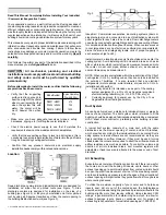
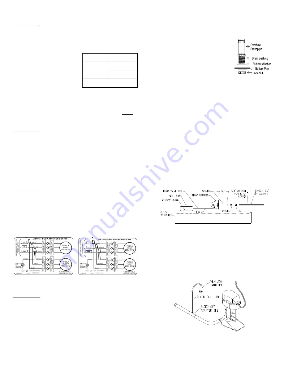
Install overflow drain bushing in bottom of cooler as follows:
!
Slide rubber washer over drain bushing.
!
Push drain bushing through bottom of
cooler, assemble and tighten lock nut.
!
Screw plastic overflow standpipe into the
drain bushing and tighten snugly (hand
tight) to prevent leakage.
!
Connect a suitable drain line (copper /
PVC / garden hose) to drain bushing.
Never drain water onto a roof; mineral
build-up or damage to roof may occur.
NOTE: Drain water in accordance with local plumbing codes.
Connect Water Supply
CAUTION: All plumbing installations must comply with
local building and safety codes, and must be performed
by qualified personnel only.
NOTE: Coolers should not be connected to “soft” water systems. Soft
water will accelerate corrosion and decrease the effective life of pads
and cooler cabinet. Connect water line as follows:
!
A water supply valve should be installed at a convenient location,
to allow the water supply to be turned on and off for servicing or
winterizing. Minimum 3/8 diameter tubing should be used to
provide water to the cooler, larger tubing is recommended if the
distance from the valve to the cooler is greater than 100 feet, then
reduced to 3/8” at the unit.
!
Install float valve in the bracket provided
.
!
Connect tubing from water supply to float valve. Place
compression nut and ferrule over end of tubing, insert tube into
float valve then tighten compression nut to secure.
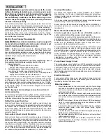
Install Bleed-off
To minimize mineral scale “build-up”use the included bleed-off
assembly. Remove the cap from the bleed-off tee; insert the black
tubing and route the tubing through standpipe opening into the drain
line
bove the water level.
(see Figure 7)
(see Figure 8). To prevent siphoning of the water, make sure that
the bleed-off tee is a
Belt Adjustment
CAUTION
: Disconnect all electrical power to the cooler
and insure that belt is not rotating before adjusting belt
tension. Do not adjust belt tension by changing diameter
of adjustable sheave. Adjust belt tension only by adjusting
motor bracket.
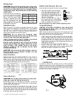
Correct belt tension and alignment
is important, proper setup reduces
power consumption and prolongs
life of belt and motor. When
installing or adjusting belt, loosen
the motor adjustment bolts and
adjust to proper tension for each
model as listed. Do not tighten belt
by adjusting motor pulley.
Adjust Motor Pulley
When the cooler is connected to extended ductwork, the cooler
capacity and motor amperage may decrease due to the increased
duct resistance. The adjustable motor pulley is to be used ONLY to
return the cooler motor to it's maximum allowable amperage and
should not be readjusted except for this purpose.
CAUTION:
Do not exceed the maximum motor
amperage (FLA) stamped on the motor specification plate
or motor can be overloaded, damaging motor.
Check amperage with all doors, windows and exhaust
vents open and/or all relief systems operating.
Improper pulley adjustment will overload and severely
damage motor windings (this damage will NOT be covered
under warranty). Only qualified persons with proper
electrical equipment and knowledge should adjust
variable pitch sheaves.
CAUTION:
Never operate unit with pad frames removed.
This will result in an overloaded condition and may
damage the blower motor.
Pump Junction Box
Recirculating Pump
CAUTION:
Do not allow pump to fall over and become
submerged; water will damage pump motor.
Recirculating pump(s) are necessary for Industrial / Commercial
cooler operation. Use pump kit number PK60LA for 115V applications
or PK62LA for 230V applications.
Mount pump junction box assembly (JBK115 for 115V pumps or
JBK230 for 230V pumps) in the location shown on page 7 for your
model. Connect pump receptacle wiring inside junction box to the
GFCI protected pump power supply wiring as shown in appropriate
wiring diagram (label attached to junction box, Figure 5).
Locate and install pump(s) in the location shown on page 7 for your
model. Plug pump cord(s) into junction box receptacle(s) and make
sure that plug is fully inserted. Place pump cord(s) into wire retainer
clips as shown (page 7), insuring that cord(s) does not touch the water
in the bottom pan or contact the wet pads.
Fig.5
Fig. 6
Fig. 8
Motor Hp Belt Tension
¾
, 1, 1
½
, 2 25 lbs
3, 5 35 lbs
7
½
, 10 40 lbs
4 UL Classified Industrial / Commercial Evaporative Cooler Use and Care Manual
Fig. 7

