UL Classified Industrial / Commercial Evaporative Cooler Use and Care Manual 7
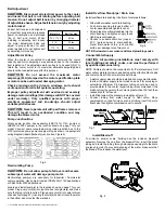
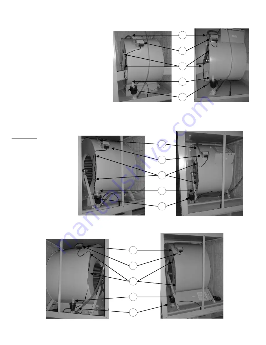
Legend
1.
Pump Cord Clips (approximate locations).
2.
Pump junction box assembly (JBK115 or
JBK230). Using “Locate J-box here” label as a
guide, position and install in indicated
location using holes in junction box flanges
as guides to locate self-drilling screws.
3.
Conduit and wiring from junction box to GFCI
protected pump electrical supply (circuit
must match pump voltage).
4.
Pump location and mounting procedure:
!
Position pump as shown for your specific
model, make sure pump sits flat on bottom.
Bend bracket as required to conform to the
mounting surface.
!
Using slotted holes in bracket as a guide,
mark and drill two 1/8” holes.
!
Secure pump with two #10 screws
(provided).
5. Route pump cord as shown, making sure cord
does touch water or wet pads and cannot be
pulled into the moving blower wheel or drive
assembly. Leave sufficient slack in cord to
create a “drip” loop just before the cord enters
pump housing.
CAUTION:
Route pump cord
through wire clips
making sure cord
does not touch
water in either the
bottom pan or the
pads in the frame.
3
2
1
4
5
3
2
1
4
5
3
2
1
4
5
D8801
H8801
D1425
H1425
D2231A
H2231

