background image

DUOMAT 9 

Installation 

79338 4.0 

23 


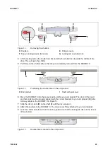
Figure 13 

Removing the shutters 

Shutters 

Fitting mounts 

Snap-in locking device (for cover) 

Locking tab on shutter lock 


Lift the locking tab on the shutter lock (

F

) and slide the shutter lock towards the middle of the 

drive. This will open the shutter. 

Pull firmly on the shutters (

D

) so that they are completely removed from the DUOMAT 9. 


Figure 14 

Positioning the double drive on the end product 

End product 

Shaft with pivot lever 


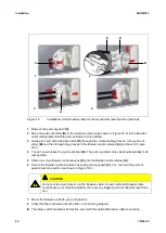
Move the DUOMAT 9 into the proper position within your end product. The slots for the head 
and foot ends must be properly aligned with the correct brackets to your end product (

H

) (refer 

to the symbols on the DUOMAT 9 in Figure 5). 

Slide the drive's slots 

(E)

 on the shaft 

(I)

 until the drive snaps in. 

Attach the shutters to the DUOMAT 9. The drive is now firmly attached to your end product. 

Lock the shutter lock (

F

) so that it locks into position (so that the locking tab (

G

) is in the recess 

of the shutter). 


Figure 15 

Double drive mounted to the end product 

 I 

Summary of Contents for Dewert Okin DUOMAT 9

Page 1: ...DUOMAT 9 Installation Instructions Translation of the original installation instructions...

Page 2: ......

Page 3: ...or the entire end product These instructions are only intended to be used by the end product manufacturer They should not be given to the operator of the end product The factual information contained...

Page 4: ...he construction of the DUOMAT 9 has been inspected by the German T V S D Product Service Inspection Authority T V S D Product Service also monitors the production of the DUOMAT 9 The official German T...

Page 5: ...t 7 1 4 Conventions used 8 2 Safety notices 9 2 1 Proper and intended usage 9 2 2 Safety notices within the installation instruction and the operating instructions for the entire machine 10 2 3 Select...

Page 6: ...ntenance 35 9 1 Maintenance 35 9 2 Cleaning and care 36 10 Disposal 37 10 1 Packaging material 37 10 2 Drive components 37 10 3 Batteries 37 Declaration of incorporation installation 38 EU Declaration...

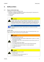
Page 7: ...eliability and lifespan of the end product CAUTION The notices in these instructions must be followed Following the guidelines during in stallation and connection procedures will help to minimize the...

Page 8: ...ty notice explanations WARNING WARNING indicates a hazardous situation which if not avoided could result in death or serious injury CAUTION CAUTION indicates a hazardous situation which if not avoided...

Page 9: ...E General ESD protective measures must be observed in accordance with DIN EN 61340 5 1 Improper usage Be sure to follow the notices below concerning improper usage You should include them in your prod...

Page 10: ...mechanism to en sure this functionality Using the drive systems in medical applications This DewertOkin product complies with the safety requirements found in IEC 60601 1 We strongly recommend that th...

Page 11: ...easures can be categorized as follows Construction measures before the installation refer to the Ensuring operational reliability dur ing installation section in Chapter Installation Safety fundamenta...

Page 12: ...e s ratings plate The ratings plate shown is an example the specifications for your drive may differ from this illus tration Figure 2 Ratings plate example DUOMAT 9 2 CARE Model name xxxxx Article num...

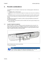
Page 13: ...on and instructions needed for these systems Only a DewertOkin device should be used to control the drive since they have already been ver ified to work together 3 1 Layout of system connections Refer...

Page 14: ...cates the location of the AUX connection for service and maintenance personnel Figure 4 Optional AUX connection label on the back of the DUOMAT 9 A DUOMAT 9 B DUOMAT 9 ER SB with mechanical reset func...

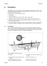
Page 15: ...ations chapter for more details about the different configurations of drives and controllers Your supplier or sales agent can also provide you with more information 4 1 Components The main components...

Page 16: ...AT 9 ER SB with mechanical reset function C DUOMAT 9 ER SB with mechanical reset function and Bowden cable retainer CAUTION The mechanical reset function operates without mains power It is not a safet...

Page 17: ...riate pluggable power supply cord is included depending on the regional version USA EURO continental Europe the UK Australia or Japan WARNING Only use the proper power cable that is permitted in your...

Page 18: ...e Drive options DUOMAT 9 DUOMAT 9 1 DUOMAT 9 2 Protection degree IPX4 Stroke 87 81 69 mm Length x width x height 733 mm x 191 mm x 131 mm 733 mm x 193 mm x 131 mm ER SB Axle gap distance 581 2 mm Diam...

Page 19: ...4 0 19 Figure 8 Dimensions of the DUOMAT 9 drive in mm Figure 9 Dimensions of the 9 DUOMAT ER SB with mechanical reset function or Bowden cable retainer in mm Figure 10 Dimensions of the DUOMAT 9 dri...

Page 20: ...ot lever Figure 11 Pivot lever in mm an example Only use a pivot lever with the proper dimensions Make sure that you consider the amount of torque that is generated by the drive when you de sign the w...

Page 21: ...ve in the end product so that it is properly aligned This will help pre vent shear stress Do not position the drive at a slanted angle when installing it in the end product A slanted angle between the...

Page 22: ...B Handholds C motor cap CAUTION Electrical components should be connected or disconnected only when the mains power cord and the battery plug when present are unplugged 1 Move your product into a posi...

Page 23: ...end product H End product I Shaft with pivot lever 6 Move the DUOMAT 9 into the proper position within your end product The slots for the head and foot ends must be properly aligned with the correct...

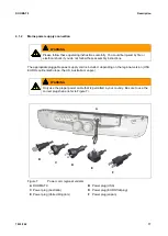
Page 24: ...continental Europe the UK or Australia Only use the proper power cable that is permitted in your country Be sure to use the correct plug shape refer to Figure 7 The power cord K should be plugged into...

Page 25: ...applied before the device actually turns on Wait at least seven seconds before beginning the commissioning 6 2 2 Option mechanical reset function with Bowden cable attachment Figure 17 Mounting the dr...

Page 26: ...lease the push out slider B The push out slider move back automatically to its rest position 5 Slide one or two Bowden cable sleeves E onto the Bowden cable retainer A 6 Secure the Bowden cable in pos...

Page 27: ...ables be sure that the cables cannot get jammed no mechanical load such as pulling pushing or bending will be put on the cables and the cables cannot be damaged in any way Fasten all cables especially...

Page 28: ...tlet 3 Loosen the screws of the motor cap and remove the motor cap from the DUOMAT 9 by pulling firmly on the two handholds 4 Remove all connecting cables such as slave drives controller keypad batter...

Page 29: ...for intermittent operations Intermittent operation is an opera tional mode where the drive must pause after a specified maximum period of operation power on time This protects the drive from overheat...

Page 30: ...set func tion B Attachment for the Bowden cable C Mechanical reset function rotary switch D Normal mode position E Symbol Lower the foot section F Symbol Lower the head section G Symbol Lower the foot...

Page 31: ...nical reset function rotary switch for head and foot sections Figure 20 Mechanical reset function at the rear of the DUOMAT 9 Switch position Function Lowering head section Lowering foot section Lower...

Page 32: ...eset function at the rear of the DUOMAT 9 Switch position Function Lowering head section Normal mode The DUOMAT 9 with adjustable head section features only the Normal mode B and Lower head section F...

Page 33: ...the rotary switch so that the desired section of your end product is selected Lowering head section Lowering foot section optional Lowering head and foot sections optional Normal mode Depending on the...

Page 34: ...ple may have trig gered or is defective Remove the power plug and allow the drive system to rest for 20 to 30 minutes Thermocouple may have trig gered or is defective Please contact your supplier or s...

Page 35: ...hs Look over the cables for any signs of damage Check the connecting cables for pinching or shearing Also check the strain relief and kink protections mechanisms in particular after any mechanical loa...

Page 36: ...cess NOTICE Never clean the drive in an automated washing system or with a high pressure cleaner Do not allow fluids to penetrate the drive Damage to the system could result 1 Always disconnect the ma...

Page 37: ...etal and plastic parts You should observe all corresponding national and regional environmental regulations when disposing of the DUOMAT 9 The disposal of the product is regulated in Germany by Elektr...

Page 38: ...7 1 5 8 1 5 9 1 5 10 1 5 13 You may only operate this incomplete machine after you have confirmed that the end product into which this machine will be installed complies with the Machinery Directive...

Page 39: ...s Electromagnetic Compatibility Directive 2014 30 EU Low Voltage Directive 2014 35 EU RoHS Directive 2011 65 EU of the European Parliament and of the Council of 8 June 2011 on the restriction of the u...

Page 40: ...against electrical danger EN60601 1 Section 11 1 Overheating protection EN60601 1 Section 11 2 Fire prevention EN60601 1 Section 11 3 Design requirements for fire resistant housing EN60601 1 Section 1...

Page 41: ...1 2 52 Section 201 9 8 3 2 Static load EN60601 2 52 Section 201 11 1 1 Temperatures EN 60601 2 52 Section 201 11 6 5 101 Waterproof protection EN 60601 2 52 Section 201 11 8 Loss of power e g using a...

Page 42: ......

Page 43: ......

Page 44: ...DewertOkin GmbH Weststrasse 1 Kirchlengern 32278 Germany Tel 49 5223 979 0 Fax 49 5223 75182 http www dewertokin de Info dewertokin de ID No 79338...

Reviews: