www.hartmann-electronic.com
Rev. 1.2
14
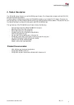
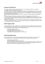
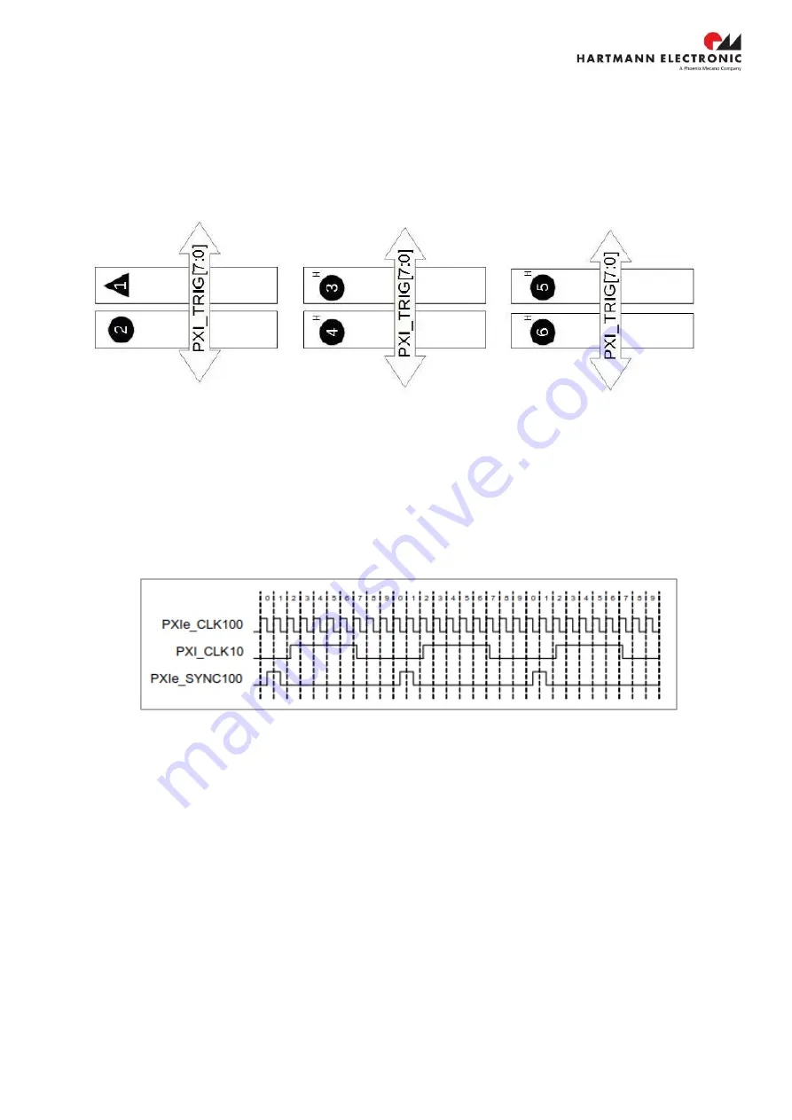
PXI Trigger Bus
All slots share eight trigger lines.
Figure 2-5
shows the PXCe4006 series backplane’s Trigger interface.
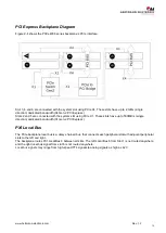
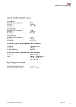
System Reference Clock
The PXCe4006 Chassis chassis supplies PXI_CLK10, PXIE_CLK100, and PXIE_SYNC100 independently driven
to each slot.
PXI_CLK10, PXIe_CLK100 and PXIe_SYNC100 have the default timing relationship according to
PXI-5 PXI
Express Hardware Specification.
The timing relations are as shown in Figure 2-6.
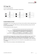
The PXCe4006 Series Chassis provides an external 10 MHz, PXI_CLK10 SMB Clock input. If a Clock signal is
detected on the rear panel SMB connector, the backplane automatically phase-locks the PXI_CLK10,
PXIE_CLK100, and PXIE_SYNC100 signal to this external clock input and distributes the clocks to all slots.
Additionally a 10 MHz clock is distributed through the backplane to an external SMB Connector (10 MHz Clock
Out).
The backplane allows the 10 MHz reference clock to be derived from an external SMB clock input or an internal
clock oscillator.
Figure 2-7 shows the Clock architecture of the PXCe4006 Series Chassis.