


Rev. 1.3
8
https://www.hartmann-electronic.com/
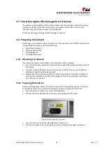
3.2
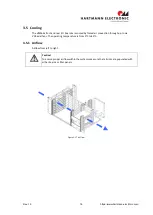
Subrack
VME64x subrack, black coating outside (RAL9005), shielded with IEEE guide rails and ESD clip
mounted on the right side.
3.3
Backplane
All Hartmann VMEbus boards are based on the HIGH-SPEED DESIGN concept. Low reflection
is achieved by means of uniform signal line surge impedance.
Shielding of each individual signal line assures minimal coupling and therefore guarantees
trouble-free operation even when expanded to the 64-bit mode with the 2e protocol (160
MByte/s).
Termination
In order to prevent interference on signal lines which might result from reflection at open
line ends, these lines must be terminated on the VMEbus. ON/IN-board (on the backplane) or
OFF-board (external) termination is possible. A distinction is made between passive and
active termination. The advantage of active termination is reduced closed-circuit current
consumption. Passive termination features better frequency response and a wider
temperature range.
Daisy chain wiring
A distinction is made between manual daisy chaining and automatic daisy chaining.
Automatic daisy chaining works without jumpers, i. e. the user does not need to bother with
plugging in and removing jumpers.
CHASSIS GND connection
There is a solid electrically conductive chassis GND surface in the backplane- to-card rack
mounting area. This guarantees EMC-tight mounting of the bus board on the card rack.
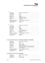
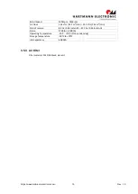
3.3.1
Description
The backplanes are optimised for the assembly of horizontal systems with backplanes
installed horizontally.
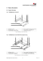
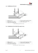
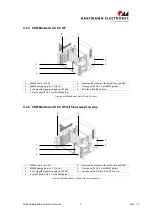
The backplanes in the VME64x system platform Basic are 9U height and includes two areas. A
6U area with two, four or eight slot for 6U VME64x boards (J1, J2 and J0 assembled) and a 3U
area for one, two or four power supplies with a 47p connector.
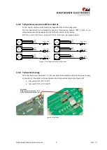
Temperature sensors for the speed control and connector terminals for fans are already
integrated.
A DIP switch facilitates selecting between two different characteristic temperature curves for
each fan:
- ON: reduced characteristic temperature curve
- OFF: Standard characteristic temperature curve
For system assemblies with a hot-swap fan tray, the fan signals are also provided by a 14-
pole plug to the fan tray.
The voltage monitoring with rest generator and AC-fail identification is located at the power
supply area.
Plug-in connecters for external connection of the JTAG and IPMB busses are also included as
standard on the backplane.


