https://www.hartmann-electronic.com/
22
Rev. 1.3
4
Installation
This section provides set up information and operation for the subrack:
•
Subrack Components
•
Inspecting the Components
•
Protection Against Electromagnetic Interference
•
Preparing the Subrack
4.1
Subrack Components
The subracks comes equipped with the following components:
•
VME64x card rack, 1U, 2U or 4U 84HP and 283mm deep, black coated outside
(RAL9005), with IEEE guide rails and ESD clip mounted on the right side
•
Up to 8-slot front and up to 8 RTM slots
•
One fan tray with alarm indicator (only order number: LMH0000310, LMH0000240 and
LMH0000260)
•
One air filter.
•
One 250W AC power supply (2 power supplies: order no.: LMH0000260 a. LMH0000180)
•
One VME64x backplane compliant with ANSI/VITA 1.1-1997specification.
4.1.1
Controls and Indicators
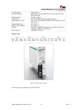
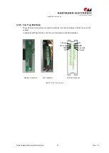
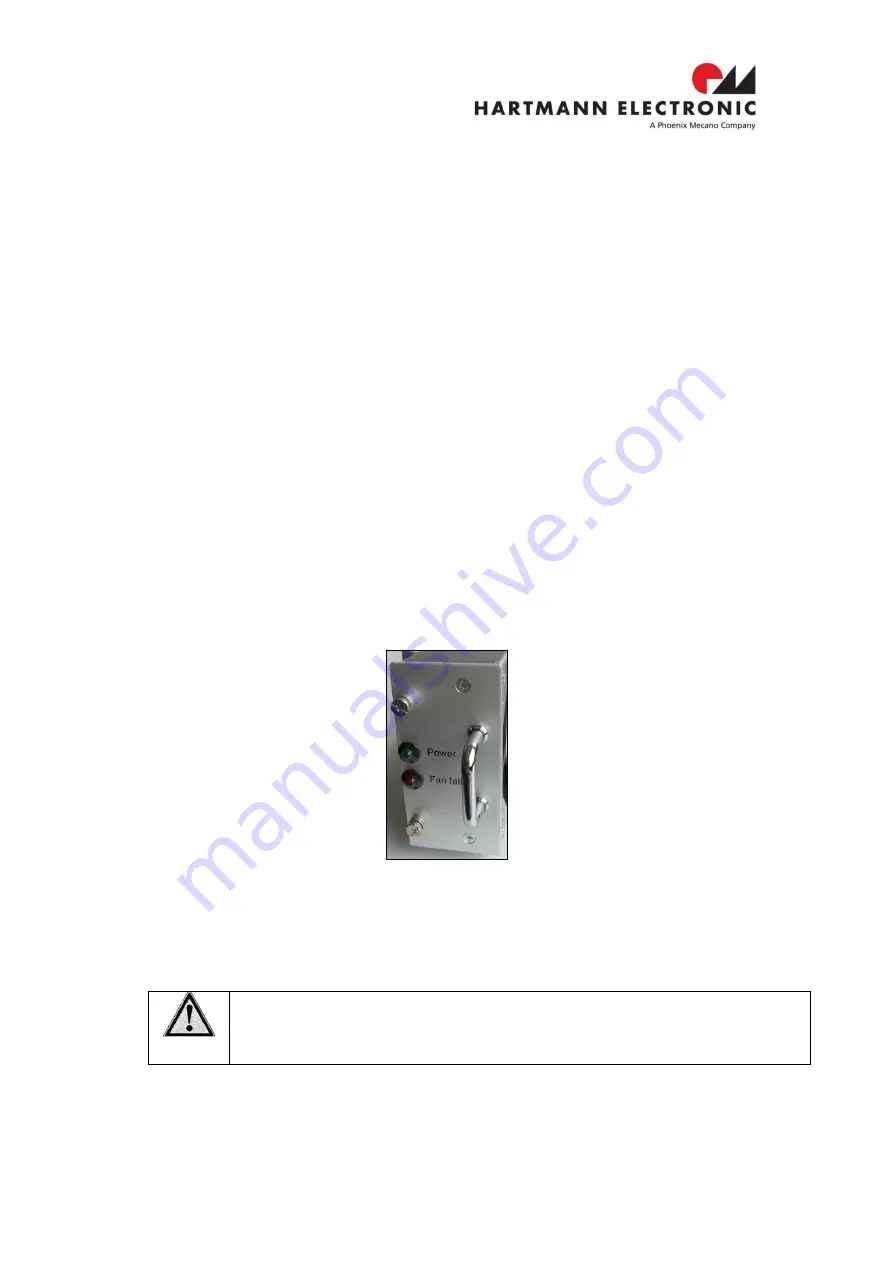
There are the following controls and indicators located on the fan tray front panel:
•
One green LED. Power OK
•
One red LED: Fan failure, one or more fun not running
Figure 4-1 Indicator Panel (sample: 2U version)
4.2
Inspecting the Subrack Components
During the course of handling, shipping, and assembly, pins, shrouds, mounting screws, fans
and other items can become damaged and/or loose.
WARNING:
Before utilizing the subrack, perform a thorough inspection to ensure the suback
and its components are not damaged.
•
To inspect the subrack:
1.
Visually inspect the subrack to ensure that all of the connector pins are straight, screws
are tight, and so on.
2.
Check to ensure none of the EMI gaskets are damaged.

