https://www.hartmann-electronic.com/
23
Rev. 1.3
4.3
Protection Against Electromagnetic Interference
The subrack contains gaskets at the shelf and board level to guard against electromagnetic
interference (EMI). Ensure that the subrack is grounded and that each of the subrack
individual components make contact with the gaskets.
Follow the proper grounding and ESD handling procedures.
4.4
Preparing the Subrack
Side flanges are provided to allow the shelf unit to be mounted in a 19” (482.6 mm) cabinet.
In preparing the subrack perform the following:
•
Mounting the Subrack
•
Powering the Subrack
•
Installing Boards
•
Installing Filler Panels
4.4.1
Mounting the Subrack
This subrack system can be installed in 19" equipment racks or cabinets
•
Ensure that the rack or cabinet is constructed to support the weight and dimensions of
the system.
•
Incorrect system installation can cause the rack or cabinet to topple over, additional
stabilization might therefore be required.
•
Single system installations should be mounted at the bottom of the rack or cabinet. In
multi system installations the bulk of the weight should be concentrated in the lower
part of the rack or cabinet.
4.4.2
Powering the Subrack
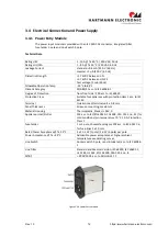
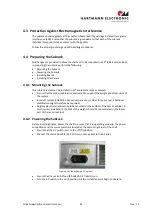
Before inserting boards, power the shelf to ensure that it is operating properly. The power
connections and the mains switch are located at the bottom right rear of the shelf
•
Ensure that the AC switch is set to the off (O) position.
•
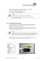
Connect the mains AC cable (C14, 10 Amp, not supplied) to the AC inlet.
Figure 4-2 AC Input (sample: 2U version)
•
Ensure that the mains AC feed (85-264VAC, 47-63Hz) is on.
•
Turn the AC switch to the on (I) position. All the system fans will begin to operate.

