Attention:
When hole diameters in the module frame are too small, an M6 screw set (Art. no. 260296) should be
used instead of an M8 screw set. In this case, use the smaller hole in the cross beam.
Now tighten all screws in the triangular sets firmly with a tightening torque of 12 Nm. It is important to ensure that the
contact surface of the ground joints runs parallel to the bottom rail. The parallel position is achieved by itself when
the ground joint is set to the lowest position on the height adjustment.
Then lift the module off the workbench and place it in its final position according to the roof coverage plan.
Note:
A plumb line can help you position the modules precisely.
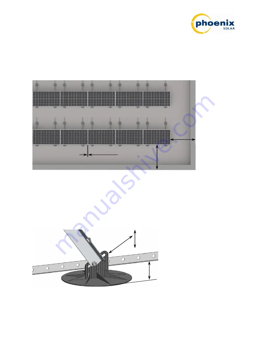
1.5 m
1.5 m
10 mm
Figure 6: Clearance and minimum distance to roof edge
A clearance of at least 10 mm should be kept between two modules. You should ensure a minimum distance to the
roof edge of 1.5 m (see Figure 6).
In the event that a ground joint is not in contact with the roof surface due to uneven roof surfaces, loosen the screw
attached to the ground joint and adjust the position of the screw by moving the elongated hole in the ground joint
(see Figure 7). This can compensate for a height difference of up to 30 mm.
30 mm
25 - 55 mm
Figure 7: Compensating for uneven surfaces
The clearance between the roof covering and the bottom rail is between 25 and 55 mm.
Status 04/12 – Subject to errors and technical modifications
Phoenix Solar AG, Hirschbergstrasse 8, 85254 Sulzemoos, Germany, Phone +49 (0)8135 938 -0, Fax +49 (0)8135 938 - 999
Page 11 of 27


