7.2 Module wiring
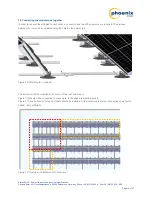
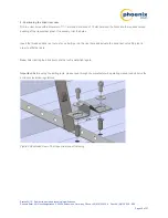
Cable the modules immediately after mounting them. Wire the module according to the wiring diagram. Cable ties
with clips are available to bundle the strings in a west-east direction. They can be attached either to the module
frame or the inner cross beam.
Note
: Measure the open-circuit voltage and insulation resistance of every string immediately after installation. This
allows potential mistakes and their sources to be quickly identified.
7.3 Mounting the ballast
Note:
Concrete paving stones are required as ballast. These are not included in the TectoFlat scope of delivery.
All types of concrete paving stone may be used which are frost resistant in accordance with DIN EN 1338 class 3
(D).
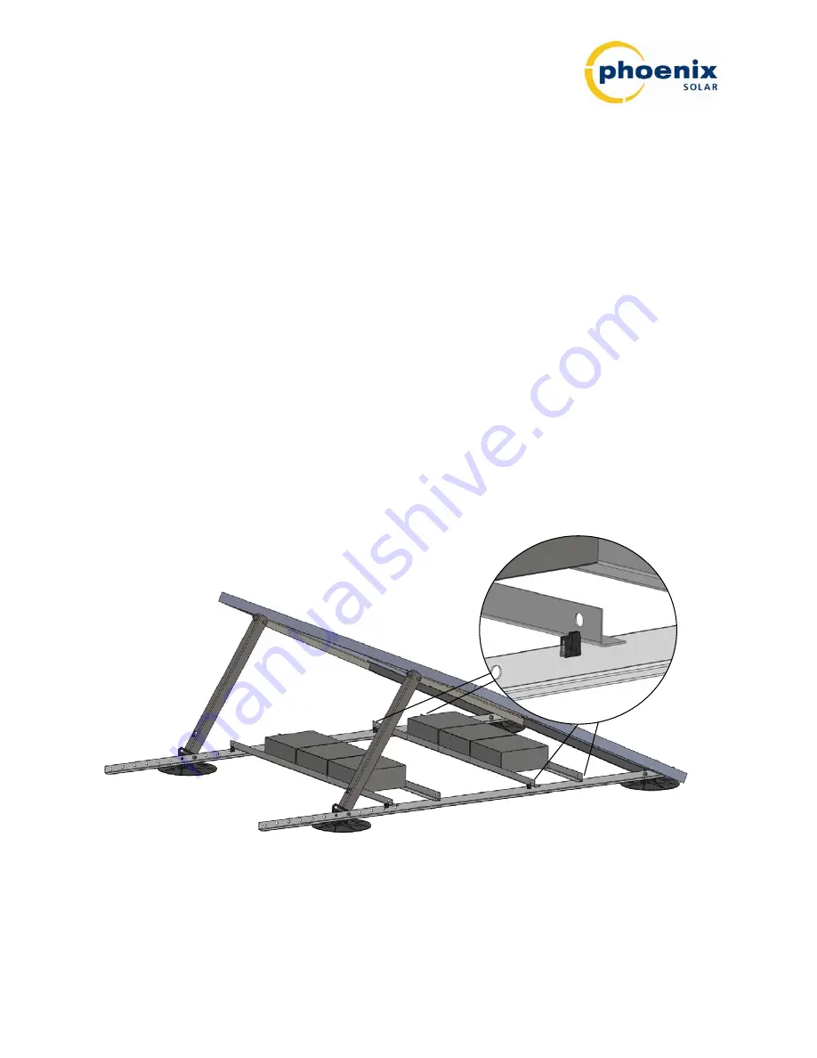
The quantity and position of the weights can be taken from the ballast plan. The ballast plan should be checked for
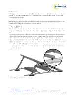
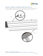
accuracy by an independent structural engineer. In order to affix the ballast, place two 1050 connectors over the
bottom rail and cover them with paving stones in such a way that they are framed by the two profile rails.
Two connectors together should not bear more than 30 kg in weight. Use two additional connectors if you have
higher ballast requirements. For loads of over 50 kg per module, the bottom rails should be supported with protection
mats, so that they only bend to a maximum degree of 5 mm.
Clamp edge clips to the bottom rail on the outside next to the connectors, in order to prevent the connectors from
sliding apart (see figure).
Figure 8: Affixing the ballast with 2 x 21.6 kg
Status 04/12 – Subject to errors and technical modifications
Phoenix Solar AG, Hirschbergstrasse 8, 85254 Sulzemoos, Germany, Phone +49 (0)8135 938 -0, Fax +49 (0)8135 938 - 999
Page 12 of 27


