8. Lightning protection
8.1 External lightning protection and grounding
If the building is equipped with an external lightning protection system then the solar system must be connected to it
over the shortest possible path (according to DIN VDE 0185 Lightning Protection System). If this is not possible then
(with reference to the regulations for antenna systems) this conductor can be connected internally through the
building – but not through rooms and areas containing inflammable or explosive materials. To avoid flashover and
induction dangers, the conductor must be kept away from other electrical circuits.
To avoid lightning flashovers, make sure to maintain a separation distance between the solar energy system and the
lightning conductor.
Calculation of the separation distance:
S = ki* (kc / Km)* i (m)
S = separation distance
kc = coefficient, dependent on the geometric arrangement
ki = coefficient, dependent on the selected lightning protection class
Km = coefficient, dependent on the material in the separation
If the building does not possess a lightning protection system then it is currently a matter of contention as to whether
the DIN VDE 0855 standard can be applied to solar systems. If this standard is used, the mounting system and the
module frames must be grounded. If the DIN VDE 0855 standard is not used then the solar generator does not need
to be grounded. However, connection to the building grounding is always recommended. Conversely, when using
transformerless inverters (e.g. with all SMA inverters with a "TL" suffix in the product name) all conducting parts of
the solar system and the mounting system must be grounded. If the system is not grounded then this can result in
capacitive voltages that are dangerous to humans. The grounding can be achieved (e.g.) via the system connection
to the equipotential bonding bar of the house or via an external grounding stake.. Type NYM-J or NYY-Y grounding
cables with a minimum cross section of 16 mm² satisfy the current regulatory requirements. The grounding device to
which the solar system is connected must be tested for correct operation.
werden. The results of this test should be recorded in a test or commissioning log for the system.
8.2 Internal lightning protection – Overvoltage protection
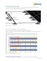
The internal lightning protection minimises damage caused by overvoltages that may occur. Impermissibly high
voltages at the solar modules can be reduced via simple measures when laying the module cables. In the case of a
lightning strike near to the solar modules the extremely high rate of change of current from the lightning can induce
high induction voltages across the mounted modules and module cables.
Attention: The larger the effective area generated by the modules and cables, the higher the induced voltage.
This type of overvoltage can be reduced through careful consideration when laying the DC cables.
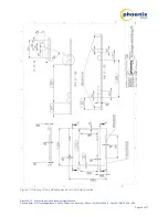
Figure
14
shows an unsuitable cable layout that can result in very high induction voltages capable of destroying the
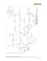
solar modules and the inverter. Figure 16 shows a correct cable layout that reduces the effective area generated by
the cables and thus reduces the danger to the solar modules and inverter.
Status 04/12 – Subject to errors and technical modifications
Phoenix Solar AG, Hirschbergstrasse 8, 85254 Sulzemoos, Germany, Phone +49 (0)8135 938 -0, Fax +49 (0)8135 938 - 999
Page 15 of 27


