6. Adjusting the tilt angle
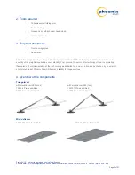
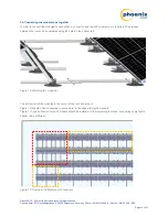
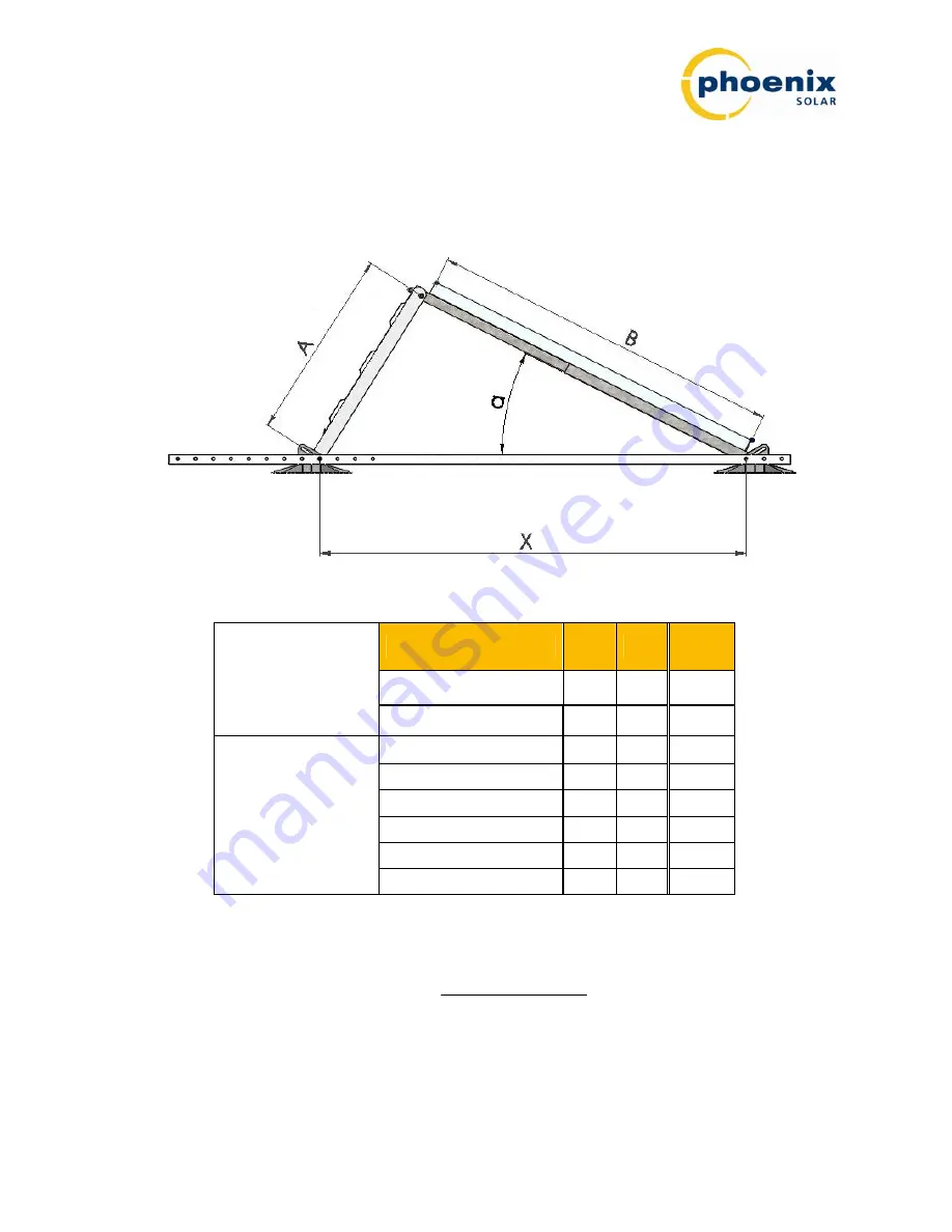
The tilt angle of the module can be adjusted in two ways:by adjusting the distance between the ground joints and
using elevation rails
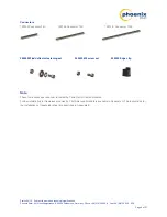
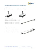
of varying lengths. The elevation rail is available in two variants: 380 and 540. They vary in
length. See dimension A in Figure 2 and Table 1. Several different module tilt angles are possible for each elevation
(see Table 1).
Figure 2: Dimensions and tilt angle
Module width W [mm]
800
1,000
1,000
Elevation rail A [mm]
540
540
380
Hole spacing X [mm]
1,100
28.3°
29.1°
20.2°
1,150
25.7°
28.0°
19.1°
1,200
22.7°
26.7°
17.6°
1,250
25.1°
15.7°
1,300
23.3°
Tilt angle
α
[°]
1,350
21.3°
Table 1:
Possible module tilt angles of framed modules
In case of strongly differing module widths, the tilt angle can generally be calculated using the law of cosines:
)
30
(
2
)
30
(
arccos
2
2
2
W
X
A
W
X
Note
: Framed modules with a width of between 800 and 1,050 mm can be installed.
Status 04/12 – Subject to errors and technical modifications
Phoenix Solar AG, Hirschbergstrasse 8, 85254 Sulzemoos, Germany, Phone +49 (0)8135 938 -0, Fax +49 (0)8135 938 - 999
Page 8 of 27


