this value to at least
1
minute. When set to 0 the unit will dial back-to-back calls without the pos-
siblity of calling in to acknowledge an alarm. The Intercall Delay can be set from 0–60 minutes.
Test Dial Tone:
The IMS-4000 can be programmed to test periodically for dialtone to ensure
that the telephone line is alive in the event that the unit has to dial out for an alarm. If the unit
determines that a dialtone is not present, it will send a diagnostic alarm via e-mail and/or SNMP
to profiles that are set up to receive diagnostic alarms (i.e. diagnostic class). Check to enable, then
enter the test interval, in hours, in the
every X hours
box.
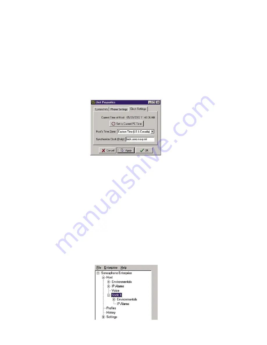
Finally, select the
Clock Settings
tab. To set the time in the IMS Host, click the button labeled
Set to
Current PC Time
. Next, select the
Host’s Time Zone
according to its location. If you would like the
unit to synchronize its time on a daily basis, enter the IP address of a compatible time server.
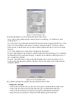
Figure 11: Clock settings tab
The IMS-4000 can be programmed to synchronize its clock to a reference time server every night
at midnight. To use this feature the IMS-4000 must have network access to a server which supports
one of the following time code protocols:
Network Time Protocol - NTP (RFC-1035)
Time Protocol - TP (RFC-868)
Daytime Protocol - DP (RFC-867)
Click the
Clock Settings
tab. Enter the name or IP address of the time server in the
Synchronize
Clock
field. To disable this feature, delete the name or IP address.
Note
: After setting the time zone, you must reboot for the new settings to take effect.
Adding a Node
Once the node has been connected to the network and the Local Configuration has been performed,
it will automatically start communicating with the Host. From the IMS Consoleview the Node will
appear within the tree. See figure below.
Figure 12: Structure tree with Node
IMS-4000 Manual
46
Summary of Contents for Sensaphone IMS-4000
Page 1: ...IMS 4000 User s Manual Version 2 4 8 PHONETICS INC SENSAPHONE ...
Page 44: ......
Page 59: ......
Page 60: ......
Page 102: ......
Page 106: ...IMS 4000 Manual 106 ...
Page 135: ...Chapter 7 IMS 4000 Sensors 135 ...
Page 146: ...IMS 4000 Manual 146 ...
Page 148: ...IMS 4000 Manual 148 ...
Page 158: ...IMS 4000 Manual 158 ...
Page 159: ...159 ...


