Alarm Response via the PowerGate, PowerGate2, or Camera
PowerGate
When an alarm occurs, you can have PowerGate or PowerGate2 outlets automatically turn ON,
turn OFF, or CYCLE power to a device.
Cycling
will switch an outlet OFF for 10 seconds and
then switch it back ON. To set up a PowerGate, click the
Alarm Response
button on the Channel
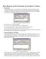
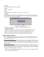
Setup Screen. A sample Alarm Response screen is shown below.
Figure 21: Alarm Response screen for PowerGate
Select Response Type
: Choose “PowerGate.”
PowerGate
: Choose the specific PowerGate you’re programming.
Outlet
: Choose the PowerGate outlet you want to program for alarm response.
New State
: Select the action you want to have occur: On, Off, Cycle.
Click the
Add
button to add this response to the list of current responses; click
Delete
to remove an
action. Repeat for as many outlets as you wish to program.
Camera Snapshots on Alarm
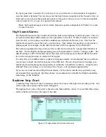
Camera images may be sent to one or more users when an Environmental or IP alarm occurs. Up
to four alarm responses (PowerGate or Camera Snapshot) may be programmed per input. To con-
figure this feature choose
Alarm Response
from the
Properties
screen for the chosen input. The
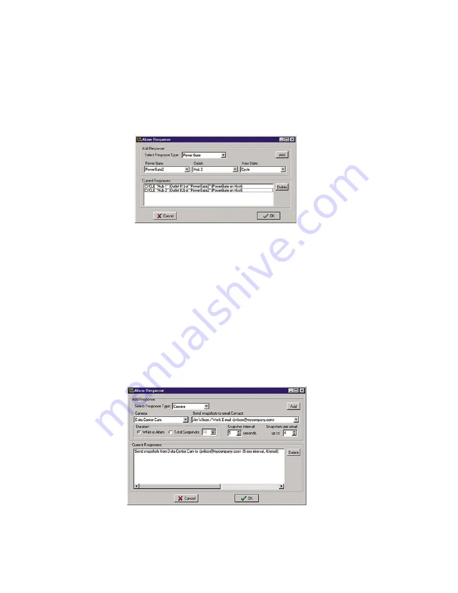
following screen will appear.
Figure 22: Camera Alarm Response
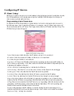
Click the down arrow in the
Response Type
menu and choose
Camera
. Select the name of the cam-
era from which you would like to receive snapshots. Next, select the E-mail address where you
would like the snapshots to be sent. There are two options to determine the
Duration
over which
snapshots will be sent. If you choose
While in Alarm
you will receive snapshots continuously until
IMS-4000 Manual
52
Summary of Contents for Sensaphone IMS-4000
Page 1: ...IMS 4000 User s Manual Version 2 4 8 PHONETICS INC SENSAPHONE ...
Page 44: ......
Page 59: ......
Page 60: ......
Page 102: ......
Page 106: ...IMS 4000 Manual 106 ...
Page 135: ...Chapter 7 IMS 4000 Sensors 135 ...
Page 146: ...IMS 4000 Manual 146 ...
Page 148: ...IMS 4000 Manual 148 ...
Page 158: ...IMS 4000 Manual 158 ...
Page 159: ...159 ...

