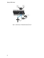
Figure 3: Locking the NEMA-4x enclosure
Antenna Information
The Skymetry WTU-14 comes with a unity-gain stub antenna
designed specifically for the frequency range required. In order
to comply with FCC RF exposure, the external antenna must be
mounted in a location where people will never come within 20cm of
the antenna. The gain of the antenna may not exceed 0dBi. For opti-
mum antenna performance, there should be no metal objects within
close proximity of the antenna.
WARNING
Do not over-tighten the antenna on the
Skymetry WTU-14; this may cause
permanent
dam-
age to the device.
The antenna
must
be connected before the device is powered up.
Connecting the Power Supply
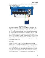
The Skymetry WTU-14 requires a 15VDC 800mA power supply
(part number FGD-8250) to operate. This power supply will charge
an external 12V battery (2–12AH) and provide the necessary power
to transmit messages over the wireless network.
WARNING
: Do not substitute supplies with lower
capacity.
Connect the positive terminal of the Power Supply to the
+Vin
ter-
minal on the Skymetry WTU-14.
Connect the negative terminal of the Power Supply to the
-Vin
ter-
minal on the Skymetry WTU-14.
Chapter 2: Installation
25
Summary of Contents for Skymetry WTU-14
Page 1: ...WTU 14 User s Manual version 1 11 Phonetics Inc LIT 0085...
Page 5: ...v...
Page 14: ...Skymetry WTU 14 Manual xiv...
Page 20: ...Skymetry WTU 14 Manual 20...
Page 32: ...Figure 11 A thermistor and a 4 20mA transducer connected to the unit Skymetry WTU 14 Manual 32...
Page 48: ...Skymetry WTU 14 Manual 48...
Page 52: ...Skymetry WTU 14 Manual 52...
Page 58: ...Skymetry WTU 14 Manual 58...
Page 64: ...Skymetry WTU 14 Manual 64...
Page 82: ...Skymetry WTU 14 Manual 82...
Page 86: ...Skymetry WTU 14 Manual 86...
Page 90: ...Skymetry WTU 14 Manual 90...
Page 98: ...Skymetry WTU 14 Manual 98...
Page 100: ...Skymetry WTU 14 Manual 100...
Page 106: ...Skymetry WTU 14 Manual 106...
Page 108: ...Skymetry WTU 14 Manual 108...
Page 109: ...Test Log...
Page 110: ......


