Wiring Sensors to Analog Inputs
The WTU-14 has 6 Analog inputs that can be used to monitor 10K
Thermistors (temperature) or 4–20mA transducers. Analog trans-
ducers are wired to the terminals labeled A1 through A6. The cor-
responding Ground terminals are located on the lower level terminal
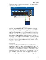
strip. The input must be configured by setting the corresponding
jumper in either the Temperature or 4–20mA position. See figure
below:
Figure 10: Input A2 configured for temp, A3 configured for 4-20mA
Temperature: The unit will accept 10K thermistors. These should be
wired to an Analog Input terminal and the adjacent ground termi-
nal. For compatible thermistors check the accessory list or thermis-
tor data in the appendices. 10K Thermistor temperature range: -60ºF
to 175ºF (-51ºC to 79ºC).
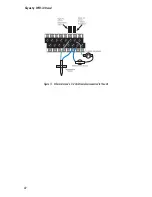
4–20mA: A 4–20mA transducer requires you to have an external
DC power supply for the transducer. Connect the positive wire of
your transducer to the positive terminal of your DC power supply.
Connect the negative terminal of the transducer to an Analog Input
terminal on the Skymetry WTU-14. Connect the negative terminal
from your power supply to the adjacent ground terminal on the
WTU-14.
Chapter 2: Installation
31
Summary of Contents for Skymetry WTU-14
Page 1: ...WTU 14 User s Manual version 1 11 Phonetics Inc LIT 0085...
Page 5: ...v...
Page 14: ...Skymetry WTU 14 Manual xiv...
Page 20: ...Skymetry WTU 14 Manual 20...
Page 32: ...Figure 11 A thermistor and a 4 20mA transducer connected to the unit Skymetry WTU 14 Manual 32...
Page 48: ...Skymetry WTU 14 Manual 48...
Page 52: ...Skymetry WTU 14 Manual 52...
Page 58: ...Skymetry WTU 14 Manual 58...
Page 64: ...Skymetry WTU 14 Manual 64...
Page 82: ...Skymetry WTU 14 Manual 82...
Page 86: ...Skymetry WTU 14 Manual 86...
Page 90: ...Skymetry WTU 14 Manual 90...
Page 98: ...Skymetry WTU 14 Manual 98...
Page 100: ...Skymetry WTU 14 Manual 100...
Page 106: ...Skymetry WTU 14 Manual 106...
Page 108: ...Skymetry WTU 14 Manual 108...
Page 109: ...Test Log...
Page 110: ......


