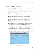
Figure 2: Output properties showing pump control
Next, click on the
Pump Control
link. This will bring up the pump
mode setup screen. Next, select the type of pump control you want
to do:
=
Drain Analog Level
=
Drain Dry Contact Floats
=
Fill
Analog Level
=
Fill
Dry Contact Floats
Figure 3: Pump Mode—Analog programming
If you select one of the
Analog
modes, you will have to fill in the
Lead, Lag, and Pumps-Off fields. In
Dry Contact Float
mode these
fields are disabled. Enter the appropriate values and click
OK
or
Apply
.
Next, click on the
output
to use for Pump Control. Click the drop-
down box and scroll to the bottom to select
Pump Control
. Click
OK
or
Apply
. This will activate the Pump Control logic. Make sure
all input devices and equipment are operational and ready for use.
Skymetry WTU-14
Manual
56
Summary of Contents for Skymetry WTU-14
Page 1: ...WTU 14 User s Manual version 1 11 Phonetics Inc LIT 0085...
Page 5: ...v...
Page 14: ...Skymetry WTU 14 Manual xiv...
Page 20: ...Skymetry WTU 14 Manual 20...
Page 32: ...Figure 11 A thermistor and a 4 20mA transducer connected to the unit Skymetry WTU 14 Manual 32...
Page 48: ...Skymetry WTU 14 Manual 48...
Page 52: ...Skymetry WTU 14 Manual 52...
Page 58: ...Skymetry WTU 14 Manual 58...
Page 64: ...Skymetry WTU 14 Manual 64...
Page 82: ...Skymetry WTU 14 Manual 82...
Page 86: ...Skymetry WTU 14 Manual 86...
Page 90: ...Skymetry WTU 14 Manual 90...
Page 98: ...Skymetry WTU 14 Manual 98...
Page 100: ...Skymetry WTU 14 Manual 100...
Page 106: ...Skymetry WTU 14 Manual 106...
Page 108: ...Skymetry WTU 14 Manual 108...
Page 109: ...Test Log...
Page 110: ......

