3
E
ASY
L
ISTENER
by Phonic Ear
GETTING STARTED
I
NSTALLING
AT664 C
EILING
S
PEAKER
Please follow these recommendations to
enhance the speaker’s overall performance.
• Consult with a professional sound
contractor or electrician before installation.
• Select a ceiling position over the central
listening area for best coverage.
• Leave a distance of at least one foot from
lighting transformers to avoid interference.
• If possible, remove obstructions in the
path of the sound, or add another speaker
to cover the affected zone.
• Remove a 2 ft x 2 ft (61cm x 61cm)
ceiling tile.
• Insert the speaker unit into opening,
placing the edge of speaker onto the
ceiling grid.
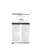
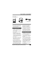
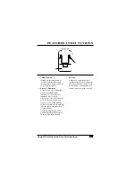
• Always attach the speaker to a structural
component above the ceiling with a min-
imum of two safety wires. (see Figure 5).
• Insert one end of the AT581 speaker cable
into the crimp connector of the ceiling
speaker wire. (Connect black to black and
red to red for correct polarity). Crimp the
connection using pliers or other tool.
I
NSTALLING THE
R
ECEIVER
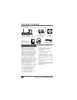
• Position the PE 210R Receiver near a
wall outlet that is central to the location
of the speakers, and verify that the power
switch is in the off position. Plug in the
AT577 Wall Transformer.
NOTE: Install your sound field receiver at
least 5 feet away from digital equipment (such
as computers or CD players) to avoid inter-
ference or possible loss in effective range.
•
Run speaker cables to the receiver, making
sure they are against a wall and out of the
way of foot traffic.
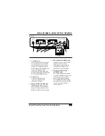
• Connect the speaker cables to the speaker
terminals on the back of the receiver.
Connect black to black and red to red for
correct polarity.
• Connect the antenna to the antenna jack
located on the back of the receiver.
• Set the FM VOL control and AUX VOL
control on the receiver to the minimum
level (counter-clockwise). Adjust the
TONE control to the center position.
NOTE: If using the PE 210FSR Receiver,
select the operating channel that matches
the transmitter channel by sliding the
channel selection switch located on the
bottom of the Receiver. (See page 6)
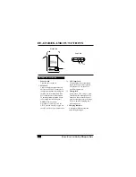
Mounted Top View
Safety Wires
Figure 5
NOTE:
GVC, SD Technologies, and Phonic Ear Inc. are not responsible for the structural integrity of the
installation. This drawing is not intended for use as an engineering design specification or for loading calculations.


