background image

PCX4000

6

English     

Rear Panel

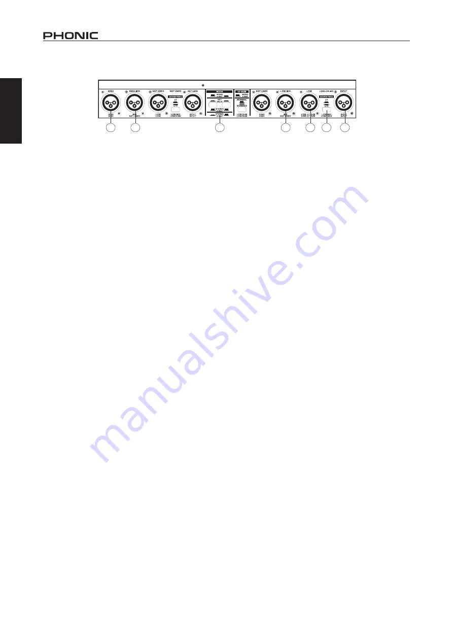
22. High Output Connectors

This connector will output the high-band signal.

23. High-Mid Output Connectors

This connector will output the high-mid-band signal.

24. Mode Buttons

These  buttons  determines  the  operating  of  the  crossover.  For 
4-way mono operation, the right button alone should be pushed 
in. Check the diagrams found with the button for other operation 
modes.

Note: 

Be sure to turn your system off before changing the setting of this 

button  as  it  produces  interference  that  may  have  a  negative  effect  on 
speakers or other equipment.

25. Low-Mid Output Connectors

This connector will output the low-mid-band signal.

26. Low Output Connectors

This connector will output the low-band signal.

27. Crossover Frequency Button

Pushing  this  button  will  raise  the  control  range  of  frequencies 
adjustable  on  the  low/low-mid  band  by  10  times  (ie.  when  the 
button is released, the control range will be between 44 and 930 
Hz; pushed-in, the range will be between 440 Hz and 9.3 kHz).

28. Input Connector

Users  can  connect  their  balanced  or  unbalanced  input  signals 
here.

APPLICATION

Measurement & Setup Tools

By  using  a  hand-held  spectrum  analyzing  tool  along  with  pink 
noise, users are able to better perfect their system’s sound. Check 
the operation manuals for your analyzer and pink-noise generator 
for many more useful tips on set up. Play the pink noise through 
your system and stand about 5 meters from your speaker to take 
measurements with the spectrum analyzer.

Setting Input Levels

The  input  level  can  be  cut  and  boost  by  up  to  6  dB.  Provided 
the  output  level  of  your  mixer  is  set  to  an  acceptable  degree, 
setting all input controls to 0 dB should be perfectly acceptable. 
In the event that the device you connect to the PCX4000’s input 
is a consumer level device (ie. signal level is as low as -10dBV), 
using the full amount of boost that the input level control allows 
may be necessary.

Setting Output Levels

Output levels of each individual band can be cut and boost by up 
to 6 dB. With the help of an analyzer, all output levels can be set 
to achieve a linear frequency response in the system. First mute 
each output, leaving the one you wish to set active, and check 
crossover frequencies and levels by playing pink-noise through 
your system. Then, when switching on an adjacent band, the level 
measured at the crossover frequency should immediately go up by 
3 dB. This can then be repeated for all output channels.

Setting the Crossover Frequency

The  first  thing  to  keep  in  mind  when  setting  your  crossover  is 

what frequencies can my speakers handle? Be sure to check your 
subwoofer,  full-range  speaker  or  driver’s  user’s  manual  before 
setting your crossover frequencies. Keeping the signal sent to the 
speaker in the frequency range ascribed in the user ’s manual will 
ensure your speakers function smoothly and correctly.

The Linkwitz-Riley filter employed by the PCX4000 uses a slope 

of  24  dB  per  octave.  It  may  be  interesting  to  note  that,  due  to 
the  Crossover  Frequency  Button  on  the  rear  of  the  device,  the 
crossover  frequency  for  the  low  frequency  band  is  adjustable 
between 44Hz and 9.3 kHz. This allows for the low output to be 
used with full-range speakers as well as subwoofer speakers.

22

23

26

25

2

28

24

Summary of Contents for PCX 4000

Page 1: ...PCX 4000 User s Manual Manual del Usuario...

Page 2: ...ENGLISH I ESPA OL II V1 1 06 01 2012 High Precision Stereo 2 3 Way Mono 4 Way Crossover Crossover de Alta Precisi n Est reo 2 3 V as Mono 4 V as PCX 4000 English Espa ol...

Page 3: ...l 1 Rear Pane 2 3 Way Stereo Operation 3 Front Panel 3 Rear Panel 4 4 Way Mono Operation 5 Front Panel 5 Rear Panel 6 APPLICATION 6 SPECIFICATIONS 8 APPENDIX DIMENSIONS 1 BLOCK DIAGRAM 2 CONTENTS USER...

Page 4: ...ing lighting storms or when unused for long periods of time 14 Refer all servicing to service personnel Servicing is required when the apparatus has been damaged in any way such as power supply cord o...

Page 5: ...red output device to the PCX4000 s input connector Commonly this would be a mixer s auxiliary or main output 3 Connect all of your required input devices to the device s output connectors Commonly thi...

Page 6: ...se Holder This connector is used to supply power to the PCX4000 through theAC cable provided along with this unit The fuse holder located below this connector is used to house the connector s fuse If...

Page 7: ...s the level of the low band output between 6 and 6 dB 7 Low Phase Invert Control This button reverses the phasing of the low band output making the signal appropriate for out of phase or incorrectly w...

Page 8: ...his is particularly helpful when including additional subwoofers to your system 22 Low Output Connector This connector will output the low band signal 23 Crossover Frequency Button Pushing this button...

Page 9: ...Low Mid Output Control This controls the level of the low mid band output between 6 and 6 dB 10 Low Mid Phase Invert Button This button reverses the phasing of the low mid band output making the signa...

Page 10: ...vel can be cut and boost by up to 6 dB Provided the output level of your mixer is set to an acceptable degree setting all input controls to 0 dB should be perfectly acceptable In the event that the de...

Page 11: ...analyzer ready 3 Adjust the bands above and below your crossover frequency so that each of them produces a 0 dB reading at the crossover frequency as read by your analyzer Mute all bands other than th...

Page 12: ...o Noise Ratio Ref 4 dBu 20 Hz to 20 kHz unweighted Stereo Mode Mono Mode Low Output 94 dB 94 dB Mid Output 94 dB High Output 91 dB 89dB Dynamic Range 106 dB unweighted THD Noise 0 04 0 5 limiter on In...

Page 13: ...nada 120V 60 Hz Europe U K Australia 230V 50 Hz Japan 100V 50 60 Hz Power Consumption 20 W Fuses 100 120 V T630 mA H 200 240V T 315 mA H Mains Connection Standard IEC receptacle Dimensions 483 x 44 x...

Page 14: ...f the date of purchase You will need it for any warranty service No returns or repairs will be accepted without a proper RMA number return merchandise authorization In order to keep this warranty in e...

Page 15: ...o aviso INTRODUCTION 1 CARACTER STICAS 1 CONFIGURACI N R PIDA 1 OPERANDO PCX4000 1 Operaci n Est reo de 2 Caminos 1 Panel Frontal 1 Panel de Dorso 2 Operaci n Mono de 3 Caminos 3 Panel Frontal 3 Panel...

Page 16: ...PCX4000 12 English Espa ol...

Page 17: ...idad est apagada Preferentemente remueva el cable de corriente alterna 2 Conecte su dispositivo de salida requerido a conector de entrada de PCX4000 En general sto ser a un auxiliar de mezcladora o sa...

Page 18: ...Dorso 14 Conector de Corriente Alterna y Portafusible Este conector es usado para suministrar energ a a PCX4000 por el cable de cor r iente al terna proporcionado con esta unidad El portafusible loca...

Page 19: ...n fase 6 Control de Salida Baja ste controla el nivel de salida de baja banda entre 6 y 6 dB 7 Control de Invertir de Fase Baja Este bot n invierte las fases de salida de banda baja haciendo la se al...

Page 20: ...vo sobre los altavoces u otro equipo 21 Bot n de Suma Baja En modo est reo pulsando este bot n combinar los dos canales de frecuencia baja y enviarlos por el canal 1 salida de frecuencia baja solo Est...

Page 21: ...er la se al de banda baja 9 Control de Salida Media Baja ste controla el nivel de salida de banda media baja entre 6 y 6 dB 10 Bot n de Invertir de Fase Media Baja Este bot n invierte las fases de sal...

Page 22: ...condici n de que el nivel de salida de su mezcladora sea seteado a un grado aceptable configurando todos los controles de entrada a 0 dB deber a ser absolutamente aceptable En el caso de que el dispos...

Page 23: ...l ruido rosa a trav s de su sistema y tenga su analizador a mano listo 3 Enmudece todas las bandas distintas de las dos que rodea la frecuencia de crossover Si las dos bandas juntas producen una lectu...

Page 24: ...3 dB ndice de Se al a Ruido Ref 4 dBu 20 Hz a 20 kHz inponderado Modo Est reo Modo Mono Salida Baja 94 dB 94 dB Salida Media 94 dB Salida Alta 91 dB 89dB Rango Din mico 106 dB inponderado THD Ruido 0...

Page 25: ...A Canad 120V 60 Hz Europa Reino Unido Australia 230V 50 Hz Jap n 100V 50 60 Hz Consumo de Energ a 20 W Fusible 100 120 V T630 mA H 200 240V T 315 mA H Conexiones Principales Est ndar IEC recept culo D...

Page 26: ...de la fecha de compra Va a necesitar este comprobante para cualquier servicio de garant a No se aceptar n reparaciones o devoluciones sin un n mero RMA apropiado return merchandise autorization En ord...

Page 27: ...PCX4000 Appendix Ap ndice measurements are shown in mm inches DIMENSIONS DIMENSIONES Todas las medidas est n mostradas en mm pulgadas 482 6 19 3 7 1 4 4 2 1 8 3 6 0 2...

Page 28: ...UTE MUTE INPUT THRESOLD LIMITER XOVER FREQ 25Hz HPF HF INPUT 2 LOW CUT NOT USED LOW LOW CUT GAIN 24dB Oct Linkwitz Riley Filter MUTE GAIN NOT USED HIGH HIGH MID MID MONE MONO CD HORN STEREO 24dB Oct L...

Reviews: