11 Pinouts
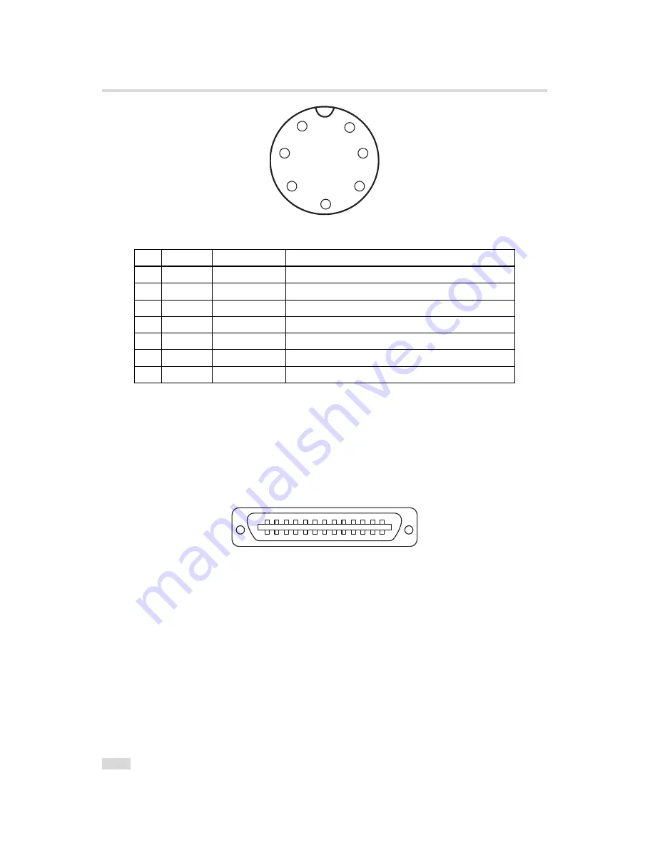
1
2
3
4
5
6
7
Figure 11.2: Power supply plug, 7-pole (rear view of plug, solder side)
Pin
I/O Type
Name
Description
1
PWR
VDD
+12 V DC (
±
10%)
2
PWR
GND
Ground
3
O
RESERVED
Do not connect
4
PWR
STROBE-VDD
+5 .. +15 V DC
5
O
STROBE
Strobe control (opto-isolated)
6
I
TRIGGER
External trigger (opto-isolated), +5 .. +15V DC
7
PWR
GROUND
Signal ground (for opto-isolated strobe signal)
Table 11.2: Power supply plug pin assignment
11.2
CameraLink Connector
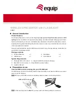
The pinout for the CameraLink 26 pin, 0.5" Mini D-Ribbon (MDR) connector is according to the
CameraLink standard ([CL]) and is listed here for reference only (see Table 11.3). The drawing
of the CameraLink cable plug is shown in Fig. 11.3. CameraLink cables can be purchased from
Photonfocus directly (www.photonfocus.com).
2
1
3
4
5
6
7
8
9
1 0
1 1
1 2
1 3
1 4
1 5
1 6
1 7
1 8
1 9
2 0
2 1
2 2
2 3
2 4
2 5
2 6
Figure 11.3: CameraLink cable 3M MDR-26 plug (both ends)
96
Summary of Contents for CameraLink MV-D1024E-160
Page 1: ...User Manual MV D1024E CameraLink Series CMOS Area Scan Cameras MAN028 03 2008 V1 3...
Page 2: ......
Page 4: ...2...
Page 8: ...CONTENTS 6...
Page 14: ...2 How to get started CameraLink 12...
Page 20: ...3 Product Specification 18...
Page 46: ...4 Functionality 44...
Page 94: ...9 Warranty 92...
Page 96: ...10 References 94...
Page 100: ...11 Pinouts 98...


