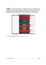
FrameCombinePulse
The
FrameCombinePulse
feature generates a pulse on the PLC_A7 after the end of a combined
frame. This signal can be used in the control of peripherical equipment by connecting this
signal to a camera output (see Section 7.10.5).
Parameters to control the
FrameCombinePulse
feature:
FrameCombine_PulseWidth:
Width of the generated pulse (
µ
s). A value of 0 turns off the
generation of pulses.
FrameCombine_PulseInvert:
False: pulse is active high. True: pulse is active low.
The
FrameCombinePulse
feature is not available in all camera revisions (see Ap-
pendix B).
The
FrameCombinePulse
feature can also be used when FrameCombine is turned
off. In this case a pulse is generated after the readout of every image.
5.1.3
Multiple Regions of Interest
The Photonfocus 2048 GigE camera series can handle up to 8 different regions of interest. This
feature can be used to reduce the amount image data and increase the frame rate. An
application example for using multiple regions of interest (MROI) is a laser triangulation system
with several laser lines. The multiple ROIs are joined together and form a single image, which
is transferred to the acquisition device.
An individual MROI region is defined by its starting value in y-direction and its height. The
starting value in horizontal direction and the width is the same for all MROI regions and is
defined by the ROI settings. The maximum frame rate in MROI mode depends on the number
of rows and columns being read out. Overlapping ROIs are not allowed and no row must be
read out more than once.
The individual ROI in a MROI must not overlap and no row should be included in
more than one ROI.
In the colour models, every single ROI should start at an even row and should
contain an even number rows to have a correct Bayer pattern in the output
image.
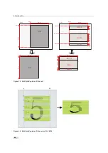
Fig. 5.3 compares ROI and MROI: the setups (visualized on the image sensor area) are displayed
in the upper half of the drawing. The lower half shows the dimensions of the resulting image.
On the left-hand side an example of ROI is shown and on the right-hand side an example of
MROI. It can be readily seen that the resulting image with MROI is smaller than the resulting
image with ROI only and the former will result in an increase in image frame rate.
Fig. 5.4 shows another MROI drawing illustrating the effect of MROI on the image content.
5.1 Reduction of Image Size
39
Summary of Contents for D/L-2048
Page 1: ...User Manual D L 2048 Camera Series CMOS camera with GigE interface MAN055 05 2015 V1 8...
Page 6: ...CONTENTS 6...
Page 14: ...3 How to get started GigE G2 Figure 3 3 PFInstaller components choice 14...
Page 34: ...4 Product Specification 34...
Page 100: ...6 Hardware Interface 100...
Page 120: ...9 Warranty 120...
Page 122: ...10 References 122...
Page 134: ...B Camera Revisions 134...


