5 Hardware Interface
5.5.2
Single-ended Inputs
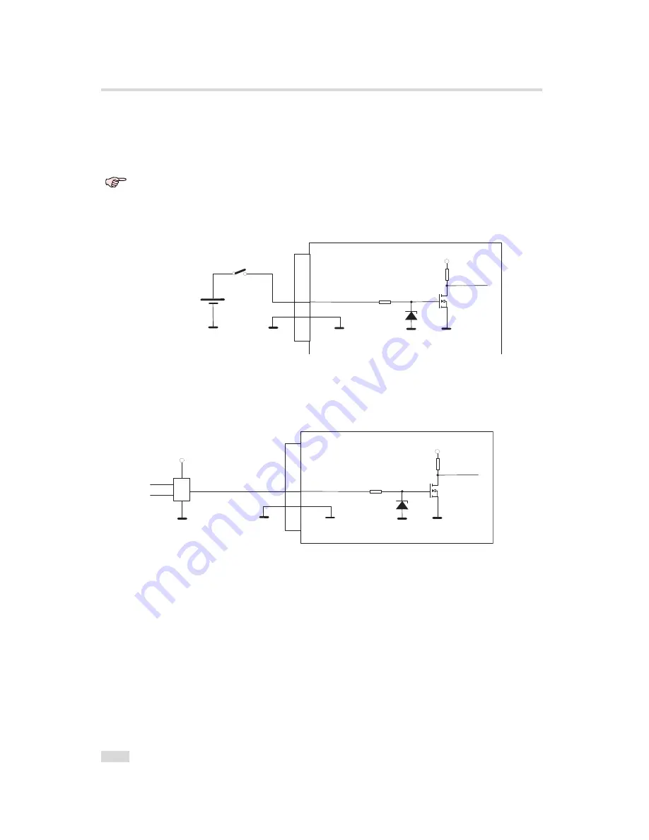
ISO_IN0 and ISO_IN1 are single-ended isolated inputs. The input circuit of both inputs is
identical (see Fig. 5.3).
Fig. 5.4 shows a direct connection to the ISO_IN inputs.
In the camera default settings the PLC is configured to connect the ISO_IN0 to
the PLC_Q4 camera trigger input. This setting is listed in Section 6.10.2.
I S O _ G N D
I S O _ G N D
I S O _ V C C
e n h a n c e d
P o w e r F E T
4 . 7 V
1 0 k
I S O _ I N 0
C a m
e r a
7
1 2 p o l . H i r o s e
C o n n e c t o r
I S O _ G N D
1 2
Y O U R _ G N D
Y O U R _ G N D
I n p u t V o l t a g e
M a x . + 3 0 V D C
M i n . - 3 0 V D C
+
Figure 5.4: Direct connection to ISO_IN
Fig. 5.5 shows how to connect ISO_IN to TTL logic output device.
I S O _ G N D
I S O _ G N D
I S O _ V C C
e n h a n c e d
P o w e r F E T
4 . 7 V
1 0 k
I S O _ I N 0
C a m
e r a
7
1 2 p o l . H i r o s e
C o n n e c t o r
I S O _ G N D
1 2
Y O U R _ G N D
Y O U R _ G N D
C o n t r o l L o g i c
&
Y O U R _ V C C
+
+
Figure 5.5: Connection to ISO_IN from a TTL logic device
.
100
Summary of Contents for DR1-D1312(IE)-G2
Page 2: ......
Page 4: ...2...
Page 8: ...CONTENTS 6...
Page 14: ...2 How to get started GigE G2 Figure 2 3 PFInstaller components choice 12...
Page 96: ...4 Functionality 94...
Page 122: ...6 Software 120...
Page 128: ...8 Warranty 126...
Page 130: ...9 References 128...


