Software Trigger
The trigger signal is applied through a software command (
TriggerSoftware
in category
AcquisitionControl
). Settings for Software Trigger mode:
TriggerMode
= On
and
TriggerSource
= Software.
Line1 Trigger
The trigger signal is applied directly to the camera by the power supply
connector through pin ISO_IN1 (see also Section A.1). A setup of this mode is shown in
Fig. 4.31 and Fig. 4.32. The electrical interface of the trigger input and the strobe output
is described in Section 5.5. Settings for Line1 Trigger mode:
TriggerMode
= On and
TriggerSource
= Line1.
PLC_Q4 Trigger
The trigger signal is applied by the Q4 output of the PLC (see also Section 5.6).
Settings for PLC_Q4 Trigger mode:
TriggerMode
= On and
TriggerSource
= PLC_Q4.
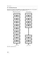
Some trigger signals are inverted. A schematic drawing is shown in Fig. 4.30.
I S O
_ I N 0
I S O
_ I N 1
P L C
L i n e 0
L i n e 1
P L C _ Q
1
P L C _ Q
4
I S O
_ O
U T 1
L i n e 1
S o f t w a r e T r i g g e r
C a m
e r a
T r i g g e r
P L C _ Q
4
T r i g g e r S o u r c e
Figure 4.30: Trigger source schematic
.
4.4 Trigger and Strobe
57
Summary of Contents for DR1-D1312(IE)-G2
Page 2: ......
Page 4: ...2...
Page 8: ...CONTENTS 6...
Page 14: ...2 How to get started GigE G2 Figure 2 3 PFInstaller components choice 12...
Page 96: ...4 Functionality 94...
Page 122: ...6 Software 120...
Page 128: ...8 Warranty 126...
Page 130: ...9 References 128...


